
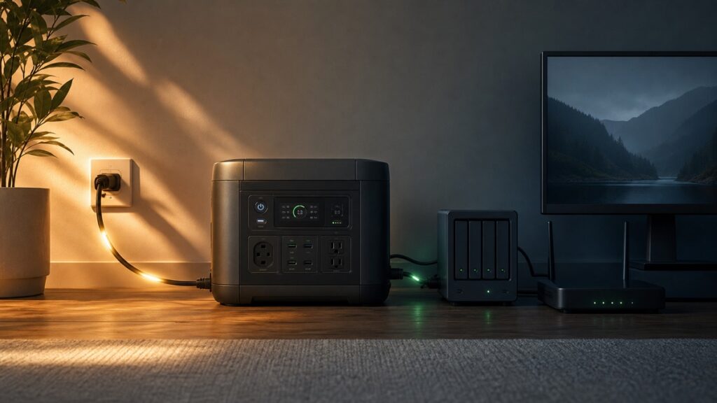
A portable power station labeled UPS or EPS is not automatically a replacement for every conventional UPS. First compare the protected device’s documented interruption tolerance with the exact station’s maximum advertised transfer time. Then confirm that the load fits both the grid-bypass path and the battery/inverter path. Finally, test grid loss, grid restoration, low-battery shutdown, and output recovery with the exact firmware, settings, wiring, and load. If the equipment requires 0 ms, a station with any non-zero transfer interval fails that requirement. If a limit is unknown, compatibility is unverified—not a pass.
Choose a documented zero-transfer design. A 10 ms or 30 ms station does not meet a 0 ms requirement.
Compare the two time values, then run the bypass, inverter, startup, and recovery checks.
Ask the equipment or power-supply manufacturer, or treat the pairing as unverified.
Follow the equipment maker’s rules and use a properly designed backup system.
The Milliseconds That Decide Whether Your Device Reboots
When acceptable grid input disappears, a standby backup source needs time to detect the event and begin supplying the load from its battery and inverter. That interval is the transfer time. The protected device may coast through a short gap using energy stored inside its power supply, or it may reset, stop a process, lose a network connection, or shut down.
The useful comparison is not “UPS versus EPS” by itself. It is the station’s maximum documented transfer interval versus the device’s documented ride-through tolerance. A lower station number creates more timing headroom, but it does not certify the complete pairing. The device’s condition, actual load, bypass limit, inverter limit, firmware, output settings, and behavior when utility power returns remain separate variables.
A 0 ms requirement creates a firm boundary. Schneider Electric documents non-zero transfer times for its line-interactive Smart-UPS families, while its specified double-conversion online families have no transfer time. It also notes that transfer behavior can cause attached equipment to reboot and recommends a double-conversion online UPS when the load requires 0 ms. That is a topology distinction—not proof that every noncritical device needs an online UPS.
Portable Power Station UPS vs EPS: Follow the Power Path
Manufacturer labels are inconsistent, so follow the electricity instead. While the grid is healthy, many stations feed the connected device from the grid through a bypass path and charge the battery. When grid input fails, a detection and transfer event moves the load to the battery/inverter path. When grid power returns—or when the battery reaches its cutoff—the station must make another decision about output state and recovery.
| Documented behavior | What it establishes | What it does not establish |
|---|---|---|
| Pass-through charging | The station can charge from an external source while supplying connected devices. | Automatic outage transfer, transfer time, or power conditioning. |
| EPS or standby UPS with a stated interval | The exact model documents automatic backup with a measurable transfer. | Compatibility with every device or a 0 ms transition. |
| Online double conversion with 0 ms transfer | The specified design has no input-failure transfer interval. | Unlimited output, unlimited runtime, or suitability without load sizing. |
Jackery’s definition of pass-through charging covers simultaneous charging and output. Its separate UPS safety guidance says its units are not true 0 ms UPS devices and publishes pass-through output boundaries for its own rated-output classes. That separation illustrates why “it powers a device while plugged in” is not enough evidence.
Run the Four-Gate Backup Compatibility Check
Use exact numbers from the protected-equipment documentation and the current station manual. Do not select a tolerance based only on whether the load is a computer, router, NAS, refrigerator, or CPAP machine. Two devices in the same category can use different power supplies, settings, and startup behavior.
The tool applies four different gates. Timing asks whether the station’s documented maximum is no longer than the load’s documented tolerance. Bypass asks whether the grid-fed path can carry the steady load. Battery output asks whether the inverter can carry the steady load and any documented startup event for its required duration. Commissioning checks what happens in the actual two-way transition.
If any required number is missing, the answer remains unverified. That is especially important for motor and compressor loads. Use the portable power station sizing workflow to establish continuous and startup demand before returning to this tool.
An Outage Has Two Transfers, Not One
An unplug test checks only the beginning of an outage. A useful commissioning exercise follows the system until grid power returns and the battery resumes its standby role. It also checks settings that can quietly defeat the plan, such as AC-output timeout, reserve level, scheduled output behavior, or output memory after shutdown.
Record bypass watts, battery state, firmware, charge limits, and which AC outputs are enabled.
Watch for a reboot, lost connection, stopped process, alarm, overload, or disabled output.
Verify warnings and the planned low-battery shutdown; do not intentionally exhaust high-consequence equipment.
Check for a second interruption and confirm that the load remains in the required state.
Confirm charging resumes and the intended AC outputs remain enabled.
Repeat after firmware, settings, wiring, battery, or load changes.
| Observed failure | Likely gate to investigate first | What not to assume |
|---|---|---|
| Device reboots only at grid loss | Transfer time and load tolerance | That more battery capacity will fix timing |
| Station overloads while grid is present | Bypass limit and combined load | That inverter surge mode applies in bypass |
| Motor fails when the outage begins | Startup demand, surge limit, and duration | That running watts describe startup |
| Everything works at grid loss but stops later | Reserve, timeout, idle-load detection, and energy plan | That passing transfer proves runtime |
| Output remains off after grid returns | Output memory, recovery setting, and firmware | That automatic transfer guarantees automatic restart |
Use Exact Model Behavior, Not the UPS Badge
The examples below are documentation snapshots accessed August 25, 2026. They show why the exact model, generation, region, and operating limit matter. They are not a ranking, and Solar Power Picks did not measure the transfer intervals.
| Exact example | Manufacturer wording and time | Separate limit or caution |
|---|---|---|
| EcoFlow DELTA 2 | EPS; switches to battery supply within 30 ms. | The manual says it does not support 0 ms switching and requires compatibility verification. US/CA bypass is specified at 13 A total. |
| EcoFlow RIVER 3 Plus | Standby UPS; transfer within 10 ms. | The documented UPS setup limits connected appliances to less than 600 W; X-Boost is unavailable in bypass. |
| Anker SOLIX C1000 Gen 2 | All AC outputs support UPS; stated 10 ms switchover. | The support statement establishes outlets and time, not a universal load guarantee. |
| DJI Power 1000 V2 | UPS mode; begins powering within 0.01 seconds. | DJI identifies the 10 ms figure as controlled-laboratory data. The original Power 1000 is documented at 0.02 seconds. |
| BLUETTI Elite 100 V2 | UPS; no more than 10 ms switchover. | The US manual separately lists 1,800 W maximum AC input for charging plus bypass. |
| APC line-interactive examples | 2–4, 6–8, or 8–10 ms depending on documented sensitivity setting and family. | A conventional UPS can also have non-zero transfer time. |
| APC double-conversion online examples | No transfer time for the specified online families. | Output, runtime, receptacles, and management still require exact sizing. |
Official documentation: DELTA 2 manual, RIVER 3 Plus manual, C1000 Gen 2 support, DJI Power 1000 V2 support, and Elite 100 V2 US manual. Recheck the exact regional manual before use because firmware and documentation can change.
Generation names are easy to misread. DJI documents 20 ms for the original Power 1000 and 10 ms for Power 1000 V2. Related EcoFlow models also use different backup descriptions and timings. Use the C1000 generation comparison and RIVER 3 versus RIVER 3 Plus comparison when model identity is uncertain, then return to the current manual.
Commission the Backup Before You Depend on It
Commissioning turns a paper candidate into a documented result for one configuration. Perform it while the return window is open, in a dry and ventilated location, with intact cords and an ordinary noncritical test load first. Read the station and protected-equipment manuals before disconnecting utility power.
- Freeze the identity. Record model, region, firmware, manual revision, settings, battery state, connected outlets, and exact load.
- Establish the steady path. Confirm the station is in its documented backup setup and the grid-fed bypass load stays below its limit.
- Check both power ceilings. Compare steady demand with continuous output and any startup event with documented surge power and duration.
- Remove grid input. Do not press station controls. Observe the protected device for reset, stopped process, lost connection, clock change, alarm, or fault.
- Restore grid input. Watch for another interruption and confirm charging resumes without disabling the required output.
- Verify timeout and reserve. Confirm low-load detection, AC timeout, reserve, warning, and shutdown settings match the use case.
- Check recovery safely. Establish what happens after low-battery shutdown and grid return without risking critical equipment or intentionally exhausting a medical load.
- Repeat after changes. Firmware, output settings, added loads, different cords, or a replacement power supply can invalidate the earlier result.
Do not create an outage test on life-support, safety-critical, business-critical, or other equipment whose interruption could cause injury, major loss, or lost data. Jackery, for example, says its portable stations are not recommended for life-support devices, data servers, or similarly consequential uses. Follow the protected-equipment manufacturer and use an appropriately engineered backup system.
For ordinary loads, commissioning still does not determine energy duration. After the transfer path passes, use the portable power station runtime model. Refrigerator startup and cycling need the separate refrigerator outage workflow; CPAP planning belongs in the CPAP backup guide.
Choose by Failure Consequence, Not by Acronym
A portable station can be a reasonable automatic-backup candidate when its documented transfer time and both power paths fit the exact load, the consequence of interruption is acceptable, and controlled loss-and-restoration tests succeed. That conclusion applies only to the tested configuration.
The decisive question is not whether the front panel says UPS or EPS. It is whether the complete documented and commissioned power path meets the protected load’s timing, power, recovery, and consequence requirements.
Leave a Reply