
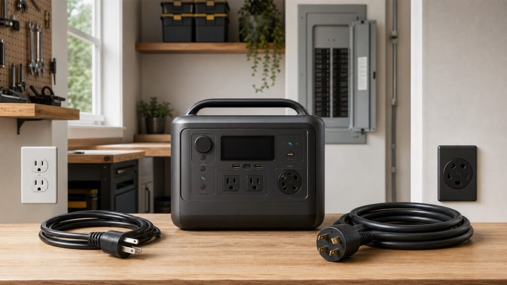
A 240V label does not automatically make a portable power station suitable for every 240V appliance or circuit. Voltage is only the first gate. The exact station must expose the correct receptacle, supply enough continuous watts and outlet current, support the intended 120V/240V mode at that moment, and provide enough usable energy for the planned duration. Start with the load nameplate and plug—not the station’s headline wattage.
The station must energize the exact voltage the load requires.
A compatible voltage without the correct documented connection is not a usable circuit.
Continuous watts, current, and any documented startup event must all fit.
Verify which outlets remain active in 120V, 240V, charging, and backup modes.
Voltage Decides Which Outlets Can Participate
In the United States, many ordinary plug-in loads use 120V while larger equipment may require 240V. A 120V-only station cannot directly supply a load whose nameplate and plug require 240V. More inverter watts do not solve that mismatch. Conversely, a 240V-capable station may still be a poor fit for a 120V RV circuit if the required 120V outlet is disabled in the selected operating mode.
Keep three ideas separate. Voltage is the electrical potential the load expects. Current, shown in amperes, is the flow the circuit carries. Power, shown in watts, is approximately voltage multiplied by current for a simple planning check, although real AC equipment can have power-factor and startup behavior that make the nameplate and manufacturer instructions more authoritative than that shortcut.
A familiar-looking outlet is not permission to improvise an adapter. Identify the load’s exact plug and the station’s exact receptacle. If they do not mate directly through a manufacturer-documented arrangement, stop. Do not defeat a grounding contact, backfeed a panel, combine outputs, or use an adapter that changes the electrical function of the connection.
Run the 120V/240V Circuit-Fit Check
This worksheet separates the voltage, current, power, mode, and energy questions. Use the current manuals for both products. If the load has a motor or compressor, enter a startup value only when the exact appliance manufacturer documents it or a qualified technician measures it with appropriate equipment.
The result can fail for several independent reasons. A 240V appliance on a 120V output fails before watts are considered. A 240V, 2,190W appliance draws about 9.1A at its stated wattage, but an exact nameplate may list a different rated current and must control the decision. A station with enough aggregate watts can still fail when its selected receptacle has a lower current limit.
Runtime is intentionally secondary. The tool reduces usable energy by the entered efficiency and reserve, then divides by average load based on duty cycle. That is a scenario estimate, not a promise: weather, thermostat behavior, voltage conversion, fan speed, inverter idle consumption, battery temperature, and aging can change the result.
Read the Load and Station Nameplates in This Order
- Required input voltage and frequency. Record the appliance’s exact values and region.
- Plug and circuit requirement. Photograph the plug, note its designation when available, and read any dedicated-circuit instruction.
- Rated watts or amps. Prefer the exact electrical nameplate and manual over a category estimate.
- Startup or inrush evidence. For motors and compressors, obtain the exact documented or properly measured event and its duration.
- Station output mode. Confirm whether 120V and 240V are simultaneous, selectable, accessory-dependent, or restricted during UPS operation.
- Outlet-level limit. Record amperes and watts for the exact receptacle, not only the station’s total inverter rating.
- Connection boundary. Direct cord-and-plug use is different from feeding an RV distribution system, transfer switch, or building circuit.
| Label | Question it answers | Common misread |
|---|---|---|
| 120/240V | Which nominal voltage modes exist? | Assuming both outlet groups work simultaneously. |
| 4,000W AC output | What total continuous output may be available in a documented mode? | Assuming every outlet can supply all 4,000W. |
| 30A receptacle | Which connector family and circuit limit apply? | Assuming all 30A receptacles have the same voltage and pin arrangement. |
| 8,000W surge | What short event the inverter may support under stated conditions? | Using surge power as a continuous rating or ignoring duration. |
| 4,096Wh | How much nominal energy the battery stores? | Treating watt-hours as inverter output watts. |
If watts and watt-hours still blur together, review watts versus watt-hours. If the load has separate running and startup demand, use the running-versus-starting-watts guide before trusting a station shortlist.
Split Phase Is a Circuit Topology, Not Extra Battery Capacity
In a typical US split-phase arrangement, two hot legs are opposite in phase. A 120V load uses one hot leg and neutral; a 240V load uses the two hot legs. That relationship explains why a product can expose both 120V and 240V connection options, but it does not tell you how the manufacturer allocates inverter power, whether the legs can be loaded asymmetrically, or whether both outlet groups remain energized.
Battery energy does not double merely because a 240V receptacle is present. A 4kWh battery remains approximately a 4kWh battery before conversion losses whether the load uses 120V or 240V. Higher voltage can reduce current for the same power, but it does not create additional stored energy.
A diagram that explains voltage relationships is not a wiring diagram. Do not connect a portable station to a panel, transfer device, inlet, RV system, or structure unless the exact products are approved for that configuration and installed according to manufacturer instructions and applicable requirements. Use a qualified electrician where required.
Mode Behavior Can Matter More Than the 240V Badge
Current manufacturer documentation shows why product identity matters. EcoFlow says the US DELTA Pro 3 can output 120V or 240V split-phase power, but not both at the same time. In 120V mode, its standard 20A and TT-30 outlets are active; in 240V mode, its L14-30 and 6-20R outlets are active instead. The practical question is therefore not merely “does it have 240V?” but “which loads remain powered in my chosen mode?”
Anker documents a different boundary for the US SOLIX F3800: when its three 120V ports are operating in UPS mode, the 240V ports do not function. That matters if a buyer imagines the same station simultaneously protecting ordinary 120V electronics and a 240V load through that UPS path.
| Exact example | Documented behavior to verify | Planning consequence |
|---|---|---|
| EcoFlow DELTA Pro 3 | Selectable 120V or 240V outlet groups; manufacturer says not simultaneous. | Map every required load to the outlet group active in the selected mode. |
| Anker SOLIX F3800 | Manufacturer says 240V ports do not operate while the three 120V ports are in UPS mode. | Do not treat the 240V receptacle as part of that documented UPS path. |
| BLUETTI APEX 300 | Confirm exact US outlet, split-phase/accessory configuration, output allocation, and manual revision. | A family-level claim cannot replace the exact connection diagram. |
These are documentation examples, not universal winners. Product pages, firmware, and manuals can change. Recheck the exact regional manual before purchase and again before commissioning. The home-backup shortlist can help identify candidates, but this circuit worksheet decides whether a candidate fits the actual load.
Commission the Exact Circuit Before an Outage
Paper specifications identify candidates. Commissioning reveals mode settings, outlet behavior, startup faults, and recovery behavior that a headline cannot. Begin with a noncritical direct plug-in load. Never use an improvised backfeed connection, and do not make a live electrical-system test outside the manufacturer-approved setup.
- Record the configuration: station model, region, firmware, battery state, output mode, exact receptacle, adapters approved by the manufacturer, and every connected load.
- Confirm voltage state: use the product display or documented indicator; qualified personnel should perform electrical measurements when necessary.
- Start at low load: energize a simple noncritical load before introducing motor, compressor, heating, or high-consequence equipment.
- Add the exact appliance: watch for overload, voltage-mode changes, outlet shutdown, unexpected power sharing, or connection heat.
- Test the intended transition: if backup behavior is required, follow the station’s approved UPS/EPS procedure and the separate UPS-vs-EPS guide.
- Run the duration scenario: confirm battery temperature, fan behavior, energy draw, reserve, and shutdown settings under realistic conditions.
- Document the result: a pass applies only to that exact setup. Repeat after firmware, outlet, adapter, wiring, or load changes.
Bottom Line: Buy the Required Topology Before More Watts
Choose a 120V-only station when every intended load and connection is documented for 120V and the outlet, continuous, startup, and runtime limits fit. Choose a 240V-capable system only when an exact load truly requires 240V or a manufacturer-approved split-phase application—and then verify the active outlets and operating mode.
Wattage cannot repair a topology mismatch. Establish the electrical path first, then size energy using the runtime guide and compare exact products only after every required circuit has a documented route.
Leave a Reply