How to charge a LiFePO4 battery with solar safely: route a compatible PV array through a correctly sized charge controller, configure that controller from the exact battery manual, and verify voltage, current, temperature, BMS, wiring, and protection at each interface. Do not connect an ordinary panel directly to the battery or assume a menu labeled “Lithium” supplies the right settings or cold-charge cutoff.
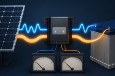
The solar path has three major devices and at least four different sets of limits. Treat it as a coordinated system, not a panel-and-battery shopping list.
Follow the Energy Path
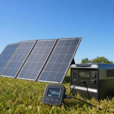
An ordinary panel is not a battery charger by itself. Irradiance, temperature, and load change its operating point, while the battery requires controlled charging behavior. Use a purpose-built regulated arrangement approved by every equipment maker; the direct-panel connection guide explains why a blocking diode or small watt label is not a substitute for regulation.
MPPT and PWM controllers manage the interface differently, but either topology still needs exact input and battery compatibility. “MPPT” does not excuse excessive PV voltage, and “LiFePO4 mode” does not prove the controller understands the battery’s current, temperature, or recovery rules.
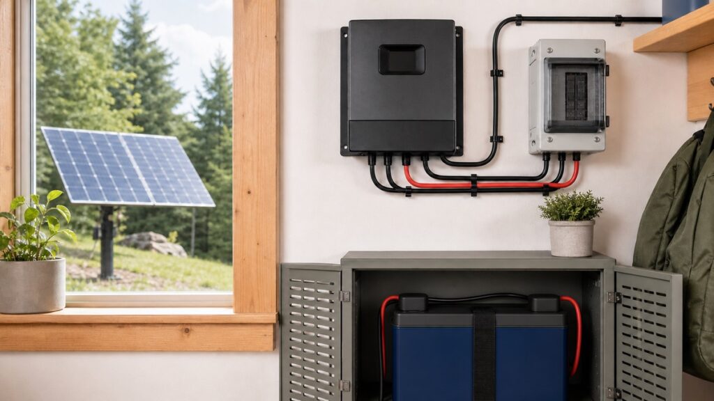
Before handling conductors, use the exact manuals for isolation, connection order, polarity verification, protection, terminal preparation, torque, grounding/bonding, and energizing. Battery fault current and PV voltage can cause fire, arc, or shock; use qualified installation when the design exceeds your training or applicable requirements demand it.
Match Four Boundaries Before Configuration
Must remain inside the controller’s absolute input ceiling; Vmp cannot replace this check.
Compare each quantity with the corresponding controller row at the chosen bank voltage.
The combined possible charge current must fit the exact battery and bank.
Map the battery manual to fields the controller can actually implement.
Array voltage is a cold-weather calculation
Add panel Voc in each series string, then correct it using the exact module’s temperature coefficient and the relevant minimum design temperature. Parallel strings do not add voltage, but they add current. The final string must also operate inside the controller’s tracking window under hot conditions, not only below its absolute maximum in cold weather.
Panel data, connector ratings, conductor design, string protection, and controller input rows all matter. Do not transfer a controller’s battery-side 30A or 40A label to the PV-input current without documentation; they describe different sides of a power converter.
Charge current belongs to the battery too
A 40A controller can be too large for one exact battery and too small to meet another system’s recovery target. Check the battery’s recommended and maximum continuous charge current, then include solar, alternator, shore charger, inverter/charger, generator charger, and any portable charger that can operate simultaneously.
Parallel batteries may increase permitted bank current only under manufacturer-approved matching and sharing conditions. Series raises voltage without multiplying string amp-hours. Recalculate controller settings and PV-watt permissions whenever bank architecture changes.
Let the Exact Battery Manual Own the Settings
Configuration rule: the battery manual defines what the bank may accept; the controller manual defines which fields and behavior it can deliver. A preset name is not the source of truth.
Battery documentation may specify a recommended charge-voltage range, current ceiling, absorption or boost behavior, float policy, balancing conditions, temperature range, and forbidden lead-acid actions. Controller interfaces may use different words for similar stages, and firmware may change available fields.
| Battery requirement | Controller field may be called | Evidence to save |
|---|---|---|
| Charge voltage | Boost, absorption, bulk target | Exact entered value and units |
| Charge-current ceiling | Output/charge limit | Solar plus overlapping sources |
| Stage duration or exit | Boost time, tail current, adaptive stage | Trigger and transition behavior |
| Float policy | Float, standby, storage | Result after the main charge stage |
| No equalization | Equalize, recondition | Positive proof the function is disabled |
| Cold-charge restriction | Charge inhibit, low-temp cutoff | Sensor owner, trigger, recovery, failure mode |
This guide intentionally does not publish one voltage recipe. The five current 100Ah manuals already differ in recommended charge current, cold behavior, and stage wording. Use the dedicated solar charge controller settings for LiFePO4 guide to perform the field-by-field mapping after identifying the exact battery.
Lead-acid temperature compensation is not the same as lithium low-temperature charge inhibition. One changes charge voltage; the other stops charge current when required. Likewise, using the BMS high-voltage cutoff as an ordinary stage transition is poor coordination—repeated protection trips require diagnosis.
Assign Cold and BMS Coordination
Solar is most likely to return on a cold morning, exactly when cell temperature may lag behind outdoor air. Decide which device prevents charging and how the controller behaves when the BMS refuses current.
Battery BMS owns cutoff
Confirm the exact trigger, recovery point, and whether the controller tolerates an open battery path.
- Model-specific evidence
- Log BMS and controller state
- Avoid repeated disconnect cycling
Controller or system owns cutoff
Confirm that battery-cell temperature is represented and every charge source receives the inhibit.
- Supported lithium logic
- Known sensor-failure behavior
- Solar, alternator, and AC coverage
Battery self-heats
Verify activation temperature, minimum incoming current, warm-up time, and when normal charging begins.
- Heating consumes available energy
- Short winter days matter
- Exact model only
If the battery does not include automatic low-temperature charge protection, its published temperature range still applies. The external system must positively keep it inside that range. See Can You Charge LiFePO4 Below Freezing? for the complete protection-owner check.
BMS low-voltage disconnect creates another coordination case. Some controllers cannot recognize a battery whose BMS has opened; exact manuals may require a compatible recovery or activation method. Never improvise by bypassing the BMS or applying unregulated power to an uncertain battery.
Estimate Daily Energy, Not a Guaranteed Charge Time
Solar energy is a daily and seasonal estimate. A transparent preliminary equation is:
array watts × peak-sun-hours × assumed system factor
The system factor represents modeled effects such as temperature, controller conversion, wiring, orientation, shading, charge-stage behavior, and availability. Replace it with location/equipment evidence rather than treating 70% as universal.
Hypothetical example: a 300W array, four peak-sun-hours, and a deliberately conservative 70% system factor produce:
`300W × 4h × 0.70 = 840Wh/day`
A 12.8V 100Ah battery contains 1,280Wh nominally. Moving it from a modeled 20% to 80% state of charge represents about 768Wh before refining for measurement and charge behavior. The example suggests one suitable day might cover that energy, but clouds, low winter sun, shade, heater use, controller clipping, loads running during charge, and stage taper can reverse the result.
Do not calculate charge time as `battery Ah ÷ controller amps` unless the controller can actually hold that current, the battery accepts it throughout, and concurrent loads are included. Charge current normally changes with available PV and charging stage.
Commission One Boundary at a Time
After the installation has been designed and wired under the exact instructions, commissioning should create evidence rather than a single “it works” moment.
- Before energizing: record exact models, serial/revision details, manuals, bank layout, conductor/protection design, polarity, and torque verification.
- Controller configuration: enter and read back voltage, current, stages, equalization state, temperature logic, firmware, and communications settings.
- Controlled startup: follow the exact connection/energizing sequence and observe PV voltage, battery voltage, current, stage, temperature, and fault state.
- Operating transition: observe behavior near charge completion and with representative loads without forcing the BMS into cutoff.
- Protected condition: verify cold-charge or other inhibit behavior only through a safe manufacturer-approved method.
- Saved baseline: export or photograph configuration and store dated measurements for later comparison.
Voltage at the controller can differ from voltage at the battery terminals because of connection and conductor drop. Remote sensing can help only when supported and installed correctly; it does not repair undersized wiring or a loose terminal. Compare appropriate measurements under safe conditions and stop if the discrepancy exceeds what the exact equipment instructions permit.
Unexpected heat, odor, swelling, damaged insulation, corrosion, water ingress, unstable voltage, or repeated protective trips requires isolation and qualified diagnosis. Do not keep changing settings until the symptom disappears.
Keep an Operating Record
- Daily energy: PV Wh, load Wh, starting/ending state of charge, and any backup charging.
- Charge behavior: maximum observed current, stage transitions, voltage at controller and battery, and BMS events.
- Temperature: cell-representative reading, cold inhibit/recovery, and heater operation when equipped.
- Configuration: exact saved profile, firmware, sensor locations, and change history.
- Connections: inspection and maintenance only at the interval and method required by the equipment makers.
- Exceptions: shade, snow, generator use, unusual loads, alarms, trips, or communications loss.
Before trusting the system unattended, save one commissioning record that another competent person could audit: exact manuals, calculated limits, final profile, sensor owner, protection design, startup measurements, and expected recovery behavior. That record—not a “Lithium” preset screenshot—is the proof that the solar charger was configured for the battery actually installed.