
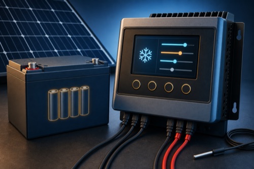
Solar charge controller settings for LiFePO4 batteries must come from the exact battery manual and be mapped to the exact controller fields; there is no universal lithium profile. Verify charge voltage, maximum current, stage duration, float policy, equalization behavior, temperature limits, sensing, and BMS coordination. A preset labeled LiFePO4 does not prove cold-charge protection.
Treat setup as a signed-off mapping between two manuals. The battery supplies acceptable behavior; the controller supplies the available controls. This guide deliberately does not publish a universal voltage preset. Its current-budget worksheet addresses one common omission: solar, alternator and AC charging can overlap even when each charger looks modest on its own.
Solar Charge Controller Settings for LiFePO4 Start With the Battery
Why Copying Another Lithium Profile Can Trip the BMS
LiFePO4 banks differ in cell count, BMS thresholds, balancing strategy, permitted current, temperature control, and intended cycle-life policy. Two nominal 12V batteries can publish different recommended charge voltages and float behavior. A value that charges one correctly can trigger another BMS or hold it at an unnecessarily high state of charge.
| Battery Manual Field | Controller Field May Be Called | Verification |
|---|---|---|
| Recommended charge voltage | Boost, absorption, bulk target | Match units and allowed range |
| Maximum charge current | Charge-current limit | Include other chargers |
| Absorption duration/exit | Boost duration, tail-current exit | Do not guess a timer |
| Float instruction | Float, standby, storage | Follow battery policy |
| Low-temperature rule | Charge inhibit/cutoff | Confirm sensor and device responsible |
| Equalization | Equalize/recondition | Ensure prohibited stages stay off |
Translate Battery Instructions Into Controller Fields
Inventory the Whole Charging System
List solar controller, alternator charger, inverter-charger, shore charger, and any portable charger. Their possible combined current can exceed the battery limit even when each is individually smaller. Also identify whether multiple batteries are connected in series or parallel under manufacturer-approved rules.
| System Fact | Record | Why It Matters |
|---|---|---|
| Battery model/revision | Exact label and manual | Prevents sibling-spec borrowing |
| Bank layout | Series/parallel count | Changes voltage and current sharing |
| Other charge sources | Max simultaneous current | Tests BMS/battery limit |
| Temperature sensing | Device and physical location | Determines whether cutoff represents cells |
| Communications | BMS/controller protocol | May enable coordinated control |
Translate Charging Stages Carefully
Controller vocabulary often comes from lead-acid charging. Bulk may mean maximum available current until a voltage target is reached; absorption or boost may hold voltage for a period; float may maintain a lower voltage. A LiFePO4 battery may permit some analogous behavior but not the same values or purpose.
Do not assume the controller’s “bulk voltage” is separately adjustable if the interface only exposes absorption. Confirm what triggers each transition and whether a timer resets after a small load event. Sustained high voltage or repeated stage cycling may be inconsistent with the battery maker’s longevity guidance.
| Term | Question to Ask | Unsafe Assumption |
|---|---|---|
| Bulk | Is this a mode or merely maximum-current phase? | Entering a universal voltage |
| Absorption/boost | What target, duration, and exit apply? | Copying lead-acid timing |
| Float | Is it permitted, reduced, or disabled? | “All chargers need float” |
| Equalization | Can it be positively disabled? | Lithium preset always disables it |
| Re-bulk/restart | What load or voltage retriggers charging? | Default hysteresis fits every bank |
Budget Simultaneous Charging Current
Set Maximum Current From the Battery Side
The controller may be capable of 40A while the battery permits only 20A, or the combined bank may allow more under defined conditions. Use the continuous charge rating and any temperature-dependent reduction. A BMS emergency cutoff should not be used as routine current regulation.
possible combined charge current = solar + alternator + AC charger + other sources
This sum is conservative when sources can operate together. If coordination guarantees that some cannot overlap, document the control logic rather than assuming diversity.
| Hypothetical Check | Input | Result | Status |
|---|---|---|---|
| Battery allowed charge current | 50A | — | Example only |
| Solar controller maximum | 30A | — | Source-specific |
| Alternator charger maximum | 30A | 60A combined | Fails unless coordinated/limited |
| Revised controlled total | 25A + 25A | 50A | Preliminary; verify all conditions |
The example does not prescribe 50A for a real battery. It shows why solar settings cannot be configured in isolation.
Add the Possible Charging Sources
For a hypothetical battery allowing 50A under the stated conditions, a 30A solar source and a 30A alternator charger can request 60A together. That leaves a 10A excess even though neither charger individually reaches 50A. Coordinated limits can change the subtotal, but the coordination must be documented and dependable. Do not assume loads will always consume the excess. Recheck the allowed battery current when temperature, bank layout or available batteries change; an isolated parallel battery can reduce the remaining bank’s capability.
Open calculation toolOptional · use your own values or a labelled example
Enter the maximum configured battery-side current from each source and the battery’s documented allowed combined current for the conditions being considered. Enter zero only when a source is absent or positively disabled. The result is a simultaneous-current subtotal, not a recommended charge rate or an assessment of cell balance. Temperature protection remains a separate prerequisite.
The interactive worksheet requires JavaScript. The worked explanation below remains available; do not treat missing output as a passed check.
Educational screening only. This worksheet cannot inspect equipment, verify an installation or approve energizing.
Assign Cold-Charge Protection to a Specific Device
Low-Temperature Charging Needs an Assigned Owner
LiFePO4 charging below the battery’s permitted temperature can cause permanent damage. Determine whether the BMS blocks current, the controller has a supported cutoff, or a coordinated device issues a charge-disable command. Then verify trigger, hysteresis, sensor location, failure mode, and restart behavior.
An internal controller temperature sensor measures the controller, not battery cells. A remote sensor attached to the wrong surface may lag or read a warmer compartment. Lead-acid temperature compensation adjusts voltage and is not equivalent to a lithium charge interlock.
| Cold-Charge Claim | Evidence Needed | Acceptable Conclusion |
|---|---|---|
| “Lithium preset” | Manual stage description | Voltage profile only unless more is stated |
| “Temperature sensor included” | Supported chemistry and control logic | Do not infer lithium cutoff |
| “Low-temp protection” | Trigger, sensor, mode, recovery | Can be assigned if exact behavior fits battery |
| “BMS protected” | Battery manual and test/commissioning method | BMS is final layer, not configuration shortcut |
Verify the Preset, Sensors and Readback
Preset or Custom Profile?
A preset is useful when its actual values and behavior match the battery manual. Read the resulting settings after selection; do not trust the label alone. Firmware and regional product revisions can change menu options.
Use a custom profile when the controller exposes every required field and the person configuring it understands stage interactions. If a required behavior cannot be disabled or a safe temperature strategy cannot be implemented, choose different equipment rather than forcing the closest numbers.
| Decision | Preset Is Suitable When | Custom Is Suitable When |
|---|---|---|
| Voltage targets | Exact resulting values match manual | All targets are adjustable |
| Stage timing | Battery permits preset behavior | Duration/exit can be configured correctly |
| Equalization | Confirmed disabled | Explicitly disabled in custom mode |
| Temperature | Separate documented protection exists | Controller supports exact required logic |
| Skill/auditability | Settings can be read and recorded | Configuration is reviewed and backed up |
Voltage Sensing, Cable Drop, and Sensor Placement
The controller may regulate voltage at its own terminals while the battery sees less because of cable drop. Remote voltage sensing can improve accuracy when supported, but it must be wired and protected according to the manual. It does not correct undersized charge conductors or loose terminals.
Place temperature sensors where the battery manufacturer directs, away from misleading heat sources. In multi-battery banks, determine how one sensor represents the coldest cells. Document sensor failure behavior: does charging continue, stop, or revert to an internal reading?
Commission and Record the Profile
After safe wiring and manual-specific energizing, confirm bank voltage selection before applying full PV. Read back every setting, record firmware and date, and compare controller voltage with an appropriate independent meter. Observe stage transitions under safe conditions rather than assuming the saved menu equals actual behavior.
Use a commissioning record:
- Exact battery and controller models/manual revisions recorded.
- Charge voltage and current fields mapped to battery instructions.
- Float, equalization, re-bulk, and timing behavior verified.
- Combined charge-source current checked.
- Low-temperature responsibility, sensor, trigger, and recovery documented.
- Voltage drop and remote sensing reviewed.
- Configuration exported or photographed where possible.
- BMS/controller logs checked for unexpected disconnects.
Maintain the Profile Across Bank and Firmware Changes
Diagnose Common Configuration Symptoms
A BMS high-voltage disconnect can reflect excessive target voltage, poor cell balance, sensor error, or wiring drop that makes the controller overshoot its local reading. Low output can simply mean the battery is near full or the controller is in a later stage. Do not change several fields at once; preserve data and compare one condition with both manuals.
| Symptom | First Safe Evidence | Escalate When |
|---|---|---|
| BMS disconnects near full | Controller/battery logs and measured voltage | Repeats or any cell exceeds manual limit |
| No charge in cold weather | Battery temperature and BMS state | Protection behavior is unclear |
| Controller stays in float | Stage rules and load pattern | Voltage conflicts with battery policy |
| Unexpected high voltage | Profile readback, sensing, terminal drop | Battery limit may be exceeded |
Multiple Batteries and Shared Current
Parallel batteries should be combined only under the battery manufacturer’s rules for model, age, state, conductors, and protection. Do not assume current divides equally through a poorly balanced bus. Series banks require a controller that supports the total voltage and a BMS architecture approved for series use.
When the bank changes, revisit the controller’s automatic voltage detection and PV-watt row. A setting suitable for one 12V battery is not automatically correct after building 24V. Record the final bank architecture beside the saved controller profile.
Settings After Storage or Firmware Changes
Long storage may call for a different state of charge or maintenance approach than daily cycling; use battery guidance. Firmware updates, controller resets, or battery replacement can restore defaults, so read back critical settings afterward. Never assume an app backup captured every hidden stage or temperature parameter.
A periodic audit should compare the saved profile with the current manuals, especially after equipment changes. It should not chase small voltage fluctuations by constantly retuning. Stable, documented settings are safer than repeated adjustment based on one day’s solar conditions.
Balance Goals and Daily Operating Targets
Some battery makers distinguish an occasional higher-voltage balancing opportunity from the preferred daily charge target. If so, implement only the documented method and confirm the controller can provide it without enabling lead-acid equalization. More time at high state of charge can trade longevity for a small amount of immediately available capacity.
Do not infer cell balance from pack voltage alone. Use BMS data and manufacturer guidance when available, and avoid raising controller voltage simply because one charge cycle ended early. A weak connection, cable drop, cold restriction, or another charger can create similar symptoms.
If balancing requires a special maintenance procedure, schedule and document it separately from the everyday solar profile. Daily charging should not repeatedly force the bank against a protection threshold in pursuit of perfect balance.
Preserve the final profile outside the phone app as a written or exported record. That copy makes recovery safer after a controller reset, replacement, or lost account.
Save a Battery-Specific Commissioning Record
Bottom Line: Configure the Battery You Actually Own
Solar charge controller settings for LiFePO4 should be a documented mapping, not a copied list of popular numbers. Start with the battery’s required voltage, current, stages, and temperature behavior; then confirm the controller and sensing system can implement them without hidden lead-acid actions.
When instructions conflict, stop and ask both manufacturers for exact-model guidance. Heat, swelling, odor, damaged wiring, unexplained overvoltage, or repeated BMS trips require isolation and qualified diagnosis. A careful profile improves charging; it does not replace safe circuit design or battery protection.

Leave a Reply