
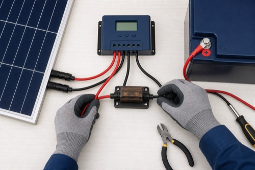
To understand how to wire a solar charge controller, begin with the exact panel, controller, battery, and inverter manuals, then design isolation, protection, conductors, polarity, grounding, and the model-specific energizing sequence. There is no universal fuse size, wire gauge, torque, or connect-first rule. Battery fault current and illuminated-array voltage remain hazardous even when another source is switched off.
Use this guide to prepare the installation record and identify questions for a qualified installer. It is not a live-work walkthrough, and it does not supply universal wire sizes, fuse ratings, torque values or grounding connections.
Wiring a Solar Charge Controller Starts With Source Isolation
Why a Clean-Looking Installation Can Still Be Unsafe
A neat cable bundle says nothing about conductor ampacity, voltage drop, fuse coordination, or terminal torque. A battery cable can deliver destructive current into a loose connection, and a PV string can remain energized whenever light reaches the modules. The controller sits between two sources, so isolation must address both.
| Document or Tool | What You Need | Why Before Wiring |
|---|---|---|
| Controller manual | Terminal map, range, torque, sequence, protection, grounding | Prevents model-to-model assumptions |
| Panel data sheet | Voc, Isc, coefficient, connectors, series fuse rating | Establishes array voltage/current |
| Battery/BMS manual | Charge limits, fault current, disconnect behavior | Defines battery-side risk |
| Circuit design | Length, ampacity, voltage drop, environment | Selects cable and protection |
| Rated test equipment | Category, leads, procedure, known operation | Supports safe verification |
Draw Every Energized Branch Before Routing Cable
Draw the Architecture Before Choosing Parts
A functional diagram should show the PV strings, combining or branch protection where required, PV disconnect, controller, battery-side disconnect and protection, battery, DC distribution, inverter, and grounding or bonding scheme. It should also show other chargers because they affect battery current and isolation.
PV strings → PV protection/disconnect → charge controller → battery-side protection/disconnect → battery bank → protected DC distribution and/or inverter
This is a conceptual path, not a placement prescription. Exact overcurrent-device location, conductor routing, bonding, and disconnect requirements depend on equipment and jurisdiction.
| Circuit Segment | Primary Design Question | Frequent Error |
|---|---|---|
| Array to combiner/controller | Cold Voc, total Isc, connector and cable rating | Treating charge amps as PV current |
| Controller to battery | Output current, cable drop, battery fault current | Long undersized low-voltage run |
| Battery to inverter | Continuous and surge current | Using controller load terminals |
| Sensor/communications | Port, polarity, isolation, routing | Plugging into a similar-looking wrong port |
Specify Protection and Terminations as a System
Plan Disconnects and Overcurrent Protection
Protection is selected to protect conductors and equipment against credible fault current while remaining coordinated with normal operation. A generic article cannot provide one fuse multiple because source behavior, wiring method, equipment listings, and code differ. The battery side deserves particular respect because its available short-circuit current can be far above normal charging current.
| Protection Item | Verify From | Decision Owner |
|---|---|---|
| PV string/array protection | Panel/controller instructions and applicable rules | Qualified designer/AHJ where required |
| Battery-side fuse/breaker | Conductor, controller, battery fault capability | System designer |
| Disconnect voltage/current rating | Actual DC circuit maximums | Designer and listed-device data |
| Enclosure/environment | Location, ingress, temperature, accessibility | Installer/design review |
DC-rated devices must interrupt the circuit voltage and current for their intended application. An AC-only breaker or informal switch is not a substitute. Confirm polarity requirements and whether a protective device can safely interrupt current in each direction.
Select Conductors That Both Perform and Fit
Conductor ampacity is only one requirement. Evaluate voltage drop, insulation temperature, bundling, conduit, ambient conditions, flexibility, chemical exposure, and mechanical support. On the low-voltage battery run, small resistance can produce meaningful voltage error and heat.
The terminal’s maximum wire size is a physical limit, not a recommendation. The calculated cable may be too large for the clamp. Use permitted ferrules, lugs, busbars, or transition devices only when the manuals and listings allow them; never cut strands away.
| Cable Check | Pass Condition | Unsafe Shortcut |
|---|---|---|
| Ampacity | Meets circuit and environment requirements | Choosing from controller amps alone |
| Voltage drop | Fits system performance target | Ignoring round-trip length |
| Terminal fit | Within published conductor range | Trimming strands |
| Bend/strain | Radius and support protect connection | Using terminal as cable support |
| Identification | Both ends labeled and polarity clear | Trusting jacket color alone |
Verify Polarity and the Exact Energizing Procedure
Establish Polarity Without Guesswork
Before energizing, isolate sources according to the equipment instructions. Trace and label each conductor, inspect connector keying, and use properly rated test equipment with a defined procedure. Verify the meter on a known source before and after the measurement when required by safe practice.
Reverse-polarity protection, when advertised, is not permission to test by trial. It may apply only to one side or one condition, and a fuse can open after damage occurs. If the measured sign or magnitude differs from the drawing, stop and find the cause.
Follow the Exact Connection Sequence
Many controllers require the battery connection first so the device can establish system voltage before PV is applied. Some require configuration before array energization; others handle detection differently. How to wire a solar charge controller correctly therefore means quoting or paraphrasing the exact manual at the work site.
A model-specific worksheet can look like this:
| Sequence Field | Exact Manual Entry | Verified By |
|---|---|---|
| Sources isolated | Page/section and method | Installer initials/date |
| First conductor/source | Exact manufacturer step | Recorded, not assumed |
| Battery voltage selection | Automatic/manual and lithium rule | Display/app check |
| PV energizing | Required condition/order | PV and battery readings |
| Shutdown order | Exact reverse or stated sequence | Label near disconnects |
Do not fill the second column from memory. Keep the manual revision with commissioning records so a future technician does not apply a sibling model’s process.
Configure and Observe the First Charge
Configure the Battery Before Expecting Normal Charging
Select chemistry and voltage values from the battery manual. Confirm maximum current, absorption or boost behavior, float, equalization, and temperature logic. Automatic bank detection may not work the same way for lithium, and a lithium preset may not implement cold-charge interruption.
Remote voltage or temperature sensors need correct placement, polarity, and compatible communications. A sensor mounted beside a warm controller may not represent cold battery cells. Document which device is responsible for stopping lithium charge in low temperature and how it reconnects.
Commission With Observations, Not Hope
Energize only in the manufacturer-prescribed order. Observe controller state, battery voltage at both battery and controller, PV voltage, charge current, error codes, and temperature. Compare readings with safe independent measurements and expected charge stage; do not expect panel nameplate watts under arbitrary field conditions.
| Commissioning Observation | Expected Source | Escalate When |
|---|---|---|
| Battery voltage | Battery/controller manual and measured bank | Values disagree materially or exceed limit |
| PV voltage | Array design and controller state | Polarity wrong or voltage outside range |
| Charge current | Irradiance, battery state, controller limit | Unexpected zero/high current after checks |
| Terminal temperature | Normal documented operation | Rapid heating, odor, discoloration |
| App/display state | Exact error table | Code repeats after prescribed action |
Retorque only if and when the manufacturer specifies it, using the stated procedure and de-energized condition. Thermal cycling can expose poor connections, but casual live tightening introduces additional risk.
Keep Loads and Service Access in the Design
Keep High-Current Loads Off the Controller Output Unless Approved
Controller load terminals are typically intended for modest DC loads with low-voltage disconnect or timer control. Their current rating is independent of charge output. Inverters, pumps, heaters, and motors can have startup current far above their steady value.
An inverter normally connects to a protected battery-side circuit sized from its own continuous and surge requirements. If a controller provides a virtual load-control signal, it may command another switching device rather than carrying load current itself.
Pre-Energizing Checklist
- Exact model and manual revision match every component.
- Cold Voc, hot Vmp, total Isc, PV watts, and output current have passed design review.
- Battery settings and low-temperature responsibility are documented.
- Conductors meet ampacity/drop requirements and fit terminals without strand removal.
- DC protection and disconnect ratings match the actual circuits.
- Polarity and conductor labels are independently verified.
- Grounding/bonding and enclosure plan meet equipment and local requirements.
- Connection and shutdown sequences are posted at the equipment.
- Controller load terminals are used only for approved loads.
- A qualified person has resolved every uncertain high-energy step.
Hand Over an Installation That Can Be Safely Maintained
Document the Installation for the Next Person
Place a durable one-line diagram and shutdown sequence near the equipment where appropriate. Record panel string layout, protective-device ratings, conductor sizes, torque values, battery profile, sensor locations, firmware, and date. Photograph concealed cable routes before panels or trim close them.
Documentation is part of safety because future troubleshooting otherwise begins with assumptions. Label optional communication cables distinctly from power conductors, and preserve exact manuals rather than a generic family brochure. If the system is modified, update the calculations and labels at the same time.
Schedule inspections only as required by the equipment and environment. Look for loosening, corrosion, abrasion, blocked ventilation, or water paths without improvising live work. Any change in smell, color, noise, or protective-device behavior deserves investigation before the system returns to normal service.
Plan for Service Without Exposing Live Parts
Locate disconnects and labels so a technician can identify and isolate PV, battery, and load circuits without reaching across energized terminals. Maintain the enclosure clearances required for covers, meters, cable bends, and ventilation. A flush installation that cannot be inspected safely is not finished merely because it looks clean.
Where several controllers or chargers share a bus, identify each source and its protective device. Confirm that opening one branch does not create a false assumption that the bus is dead. Use the approved verification process before work and keep barriers or covers in place whenever the system is operating.
Bottom Line: Wire the Exact System, Not a Generic Diagram
How to wire a solar charge controller safely is a documentation and verification process. Draw the power path, resolve both energy sources, design conductors and protection, prove polarity, configure the battery, and follow the exact energizing order. A generic drawing can explain architecture but cannot choose fuse size, torque, grounding, or sequence for every product.
If any reading conflicts with the plan, keep the circuit isolated. Heat, repeated trips, damaged material, uncertain fault current, or unfamiliar code requirements belong with a qualified installer or electrical professional, not repeated reconnection experiments.
Preserve the completed commissioning record with the equipment.

Leave a Reply