
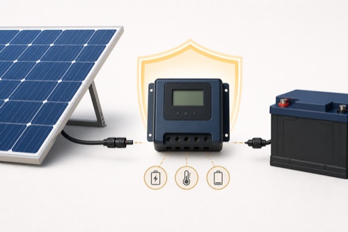
To connect solar panel directly to battery terminals is generally unsafe because an unregulated array can continue charging after the battery reaches its permitted voltage. Use a compatible charge controller or a manufacturer-designed product with integrated regulation. Low panel wattage, a blocking diode, or a battery BMS alone does not create a complete charging system.
A cable with battery clips may contain a regulator, or it may connect directly to the panel. Check the complete product instructions before treating the connection as regulated charging.
Can You Connect Solar Panels Directly to a Battery Without Regulation?
Why “It Is Only a Small Panel” Is Not a Safety Argument
People who search “connect solar panel directly to battery” are often evaluating a maintainer or emergency setup, but the same end-of-charge question applies regardless of intent.
An illuminated module produces voltage whenever conditions allow. If its operating voltage is above battery voltage, current can flow without knowing state of charge. A small current applied long enough can still overcharge a full battery, particularly when the system is unattended.
| Direct Connection Issue | Regulated System Response | Direct-Wire Gap |
|---|---|---|
| Battery reaches charge target | Controller reduces or stops current | Panel can keep supplying current |
| Chemistry needs stages | Controller follows configured profile | No stage logic |
| Night/reverse current | Equipment manages defined behavior | Depends on panel/diode/circuit |
| Temperature limit | Supported sensing/BMS coordination | No automatic control unless designed in |
| Fault/status | Controller can report and protect within scope | Little diagnostic information |
Battery Chemistry Changes the Failure, Not the Need for Control
What Can Happen to Different Batteries
Flooded lead-acid can lose water and gas when held above its intended charging behavior. Sealed lead-acid designs have less tolerance for uncontrolled gas generation. Lithium batteries may reach a BMS high-voltage disconnect, but repeatedly using that emergency boundary as the charge controller can stress components and cause abrupt cycling.
| Battery Context | Possible Direct-Charge Problem | Correct Authority |
|---|---|---|
| Flooded lead-acid | Gassing, water loss, plate damage | Battery charging manual |
| AGM/gel | Pressure, drying, shortened life | Exact sealed-battery limits |
| LiFePO4 | BMS trip, cell imbalance, cold-charge exposure | Battery/BMS instructions |
| Starter battery in storage | Chronic overcharge or under-maintenance | Approved maintainer documentation |
A discharged battery can temporarily hold voltage down and make the connection appear successful. That does not demonstrate what happens after hours of sun or after the battery fills. Safe behavior must cover the full operating cycle.
Separate a Diode From an Actual Charging Regulator
Why a Blocking Diode Is Not a Controller
A diode can prevent or reduce current in one direction, such as battery discharge into a dark panel. It cannot choose an absorption target, limit final voltage, change behavior by chemistry, or implement a lithium temperature cutoff. Its voltage drop can also change performance.
| Device | Can Block Reverse Current | Can Regulate Charge Voltage | Can Apply Battery Profile |
|---|---|---|---|
| Blocking diode | Yes, in intended direction | No | No |
| Fuse/breaker | Interrupts faults within design | No | No |
| Battery BMS | May disconnect cells for protection | Not normal PV regulation | No controller stages |
| Charge controller | May include reverse-current control | Yes, within specification | Yes, when configured correctly |
Identify an Approved Maintainer Before Calling It an Exception
Narrow Exceptions: Integrated and Purpose-Built Products
Some solar maintainers include an internal regulator and are sold for specified battery voltages and chemistries. Certain tiny devices may be explicitly approved by both equipment manufacturers for a defined use. These are designed systems, not proof that any small bare panel can connect directly.
Check the product for explicit regulated output, supported battery type, maximum capacity or use, reverse-current behavior, environmental conditions, connectors, and unattended-operation instructions. Marketing words such as trickle, smart, or maintainer are not enough without technical documentation.
| Exception Check | Evidence Required | Reject When |
|---|---|---|
| Integrated regulation | Manual describes controlled battery output | Only raw panel ratings are shown |
| Exact chemistry | Battery type/voltage explicitly supported | Generic “12V battery” claim |
| End-of-charge behavior | Voltage/stage or maintenance logic stated | No full-battery response documented |
| Environmental use | Enclosure and connection conditions | Outdoor photo without rating |
Replace the Bare-Panel Path With a Documented System
A Safer Standard Architecture
The normal path is panel or array to a suitably sized controller, then controller to battery through the required conductors, protection, and disconnects. The controller’s input must pass cold Voc, PV Isc, operating voltage, and bank-specific watt checks. Its output must match battery voltage, allowed current, profile, and temperature behavior.
PV source → PV protection/disconnect → charge controller → battery-side protection/disconnect → battery
The drawing is conceptual. Exact fuse placement, wire gauge, grounding, torque, and connection order come from manuals, system calculations, code, and qualified design where required.
Hypothetical Energy Example
Suppose a bare 20W panel could average only 8W into a battery for six hours. That is approximately 48Wh added:
8W × 6h = 48Wh
The arithmetic does not approve direct connection. It shows that “small” energy accumulates. Whether 48Wh is helpful or excessive depends on battery state, voltage, chemistry, losses, loads, and charge limits. A regulator must decide what to do as the battery fills.
Misleading Arguments to Reject
“The battery will clamp the voltage” describes temporary electrical behavior, not safe charge control. “The BMS will stop it” assigns routine regulation to an emergency disconnect. “My friend did it for years” lacks battery measurements, climate, duty cycle, and condition evidence.
Likewise, open-circuit panel voltage printed on the label is not what the battery should be exposed to. It is an input design quantity. The controller converts or switches available PV energy into a profile the battery is intended to receive.
Decision Checklist
- Is the solar product explicitly regulated for battery charging?
- Does its manual name the exact battery voltage and chemistry?
- Is end-of-charge and reverse-current behavior documented?
- Are cold Voc, available current, connectors, and conductors compatible?
- Are protection, polarity, disconnects, and environment addressed?
- Is lithium low-temperature behavior assigned to a verified device?
- Can the system be isolated and tested according to its instructions?
If the first three answers are no or unclear, do not connect the panel directly.
Check Full-Battery and Unattended Behavior
How to Replace a Direct Connection Without Guessing
Begin by recording the panel’s Voc, Vmp, Isc, Imp, Pmax, and temperature coefficient. Identify the battery’s exact chemistry, nominal voltage, permitted charging voltage/current, and temperature behavior. Then shortlist controllers whose manuals publish all corresponding boundaries. A cheap regulator with no credible PV Isc or charging-stage documentation does not resolve the original uncertainty.
The replacement controller must be sized from the array configuration, not just one module label. Series modules add voltage; parallel branches add current. Cold-correct string Voc before comparing it with the controller ceiling, and use the controller’s PV-watt row for the actual bank voltage. Confirm that the battery accepts the controller’s output together with any alternator or AC charger.
Installation deserves the same attention. A controller does not make undersized cable, reverse polarity, unprotected battery conductors, incompatible connectors, or water-exposed terminals safe. Use the exact instructions for conductor range, torque, protection, grounding, ventilation, and connection sequence.
Questions to Ask About a Solar Maintainer
For a vehicle, gate, boat, or stored battery, ask what happens after the battery reaches the target, after darkness, after a battery disconnect, and during very cold or hot conditions. Determine whether the product maintains only lead-acid or also supports the exact lithium battery. Check whether it is intended to remain connected unattended and whether its enclosure and plugs suit the location.
The word smart should correspond to documented behavior. Look for regulated output, chemistry selection, status indication, reverse-current prevention, and fault handling. If the description shows only panel Voc and watts, assume regulation still needs to be supplied separately.
A Better Acceptance Test
After a correctly designed system is installed, record battery voltage before connection, controller state after the manual-specific sequence, PV voltage, and charge current. Observe the transition as the battery approaches its target under safe conditions. Confirm that the system does not depend on the BMS repeatedly opening and that night behavior matches the instructions.
Do not use one sunny afternoon as proof of long-term safety. Verify cable and terminal temperature, settings after a power cycle, and unattended-operation behavior. Preserve the model, firmware, settings, and manual revision for future service.
Why Battery State Changes the Apparent Result
A deeply discharged lead-acid battery may hold terminal voltage low while accepting the small panel’s current, making the first test look calm. As state of charge rises, the same current can push voltage into gassing or an unsuitable maintenance condition. A lithium BMS may remain connected until one cell reaches its threshold and then open abruptly. Neither response validates unregulated charging.
Loads can disguise the problem as well. A parked vehicle alarm or gate controller may consume roughly what a small panel supplies on some days, while cloudy weather produces a deficit and bright unattended weather produces a surplus. Regulation must handle both conditions rather than relying on an accidental average.
Temperature changes battery acceptance and panel voltage. A setup that seems benign in mild weather can behave differently in winter storage or a hot enclosure. Purpose-built maintainers state their supported environment and charging behavior; a raw panel does not acquire those controls from its watt rating.
Finally, measure at the battery and understand cable drop. Long thin leads may limit current temporarily, but resistance is not controlled charge regulation and can create heat. Improving the cable later can remove that accidental limitation and expose the original overcharge risk. Design every conductor for safety and let a documented controller, not wiring loss, manage the battery.
Treat any improvised adapter as another design change. Connector polarity, current rating, environmental sealing, and strain relief must match both sides. A plug that physically mates can still reverse polarity or bypass intended protection, so use only the approved interconnection method.
Keep the purchase record and instructions with the battery. When either component is replaced, recheck compatibility instead of assuming the old maintainer or controller remains appropriate.
Choose Regulation Before Making the Connection
Bottom Line: Use Regulation Unless the Product Includes It
Can you connect solar panels directly to a battery? Only when the complete manufacturer-designed system explicitly permits it; an ordinary bare-panel charging setup needs a compatible controller. Panel size and a diode do not establish safe full-battery behavior.
The safe response to “connect solar panel directly to battery” is therefore conditional on integrated, documented regulation rather than a bare electrical connection.
Choose the controller by cold Voc, input current, output amps, bank-specific watts, and battery requirements. If battery fault current, protection, grounding, or polarity verification is outside your experience, use qualified help before energizing the circuit.
Leave a Reply