
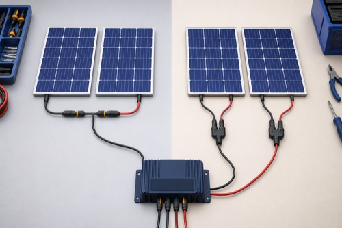
Series vs parallel solar panels for a charge controller is a trade between array voltage and current: series adds voltage, while parallel adds current for matched modules. Choose the layout only after checking cold Voc, hot Vmp, total Isc/Imp, cable loss, connectors, string protection, shade, and the exact controller’s limits. Neither arrangement is universally best.
A fixed number of identical panels can create several electrically different arrays. Series count sets the voltage sum; parallel-string count sets the current sum. The layout worksheet calculates those STC quantities separately so a 2S2P proposal cannot be mistaken for 4S1P merely because both use four panels. It does not calculate a safe final design.
Series vs Parallel Solar Panels for a Charge Controller Starts With Two Sums
Why Four Panels Can Produce Three Different Arrays
Four matched panels can be 4S1P, 1S4P, or 2S2P. Total nameplate watts remain similar, yet controller fit changes because voltage and current combine differently.
| Four-Panel Layout | Voltage Multiplier | Current Multiplier | Main Pressure |
|---|---|---|---|
| 4S1P | ×4 | ×1 | Cold Voc and hot operating window |
| 1S4P | ×1 | ×4 | PV Isc, cable, connectors, protection |
| 2S2P | ×2 | ×2 | Balanced voltage/current checks |
Use Series to Change Voltage and Parallel to Change Current
Series Wiring: Higher Voltage, One String Current
In a matched series string, current flows through every module, so string current is limited by the operating behavior of the chain. Voc and Vmp add. Higher voltage can reduce array-cable current for a given power, lowering voltage drop or permitting a different conductor design.
The cost is voltage headroom. Correct summed Voc for the coldest design condition, and check hot Vmp remains inside the controller’s operating window. One additional panel can cross the absolute ceiling even when total watts are allowed.
| Series Advantage | Series Risk |
|---|---|
| Lower array current for same power | Higher cold Voc |
| Potentially lower cable loss | One shaded module can constrain string operation |
| Fewer parallel branches | Hot Vmp may approach minimum window |
| Useful for MPPT conversion | Not suitable for low-Voc PWM input |
Parallel Wiring: Same Voltage, Added Current
Parallel strings keep approximately one string’s voltage while their currents add. This can fit controllers with low PV-voltage ceilings and may localize some shading effects. It increases current in combining conductors and through the controller input.
| Parallel Advantage | Parallel Risk |
|---|---|
| Lower array voltage | Higher total Isc/Imp |
| Branch shade may affect less of array | More connectors/combining points |
| Compatible with some PWM layouts | String protection may be required |
| Easier incremental branch addition | Input-current ceiling reached quickly |
Calculate total Isc with the exact current factors required by manuals/listing/code. Do not compare the total only with controller charge amps. Verify module maximum-series-fuse rating, reverse current, connectors, branch protection, and conductor ampacity.
Compare Complete Matched-Module Layouts
Worked 2S2P Example
Assume four hypothetical matched modules with Voc 24V, Vmp 20V, Isc 10A, and Imp 9A. A 2S2P layout produces preliminary STC values:
string Voc = 24V × 2 = 48V
string Vmp = 20V × 2 = 40V
array Isc = 10A × 2 strings = 20A
array Imp = 9A × 2 strings = 18A
array Pmax = 20V × 9A × 4 = 720W
| Quantity | Preliminary Value | Remaining Check |
|---|---|---|
| Voc | 48V STC | Cold correction and controller ceiling |
| Vmp | 40V STC | Hot condition and MPPT window |
| Isc | 20A STC | Required factors and input limit |
| Imp | 18A STC | Cable/connector operation |
| Pmax | 720W | Bank-specific controller allowance |
The example cannot produce final pass/fail without coefficient, climate, controller, battery, and installation data.
Map Identical Modules Into a String Layout
Four hypothetical modules rated at 24V Voc, 20V Vmp, 6A Isc and 5A Imp produce 48V Voc, 40V Vmp, 12A Isc and 10A Imp in 2S2P. Rearranged as 4S1P, they produce 96V Voc and 6A Isc. The nominal maximum-power total is unchanged at 400W, but a 100V controller now has very little STC voltage headroom before cold correction. A shared watt total therefore does not prove the two layouts fit the same input.
Open calculation toolOptional · use your own values or a labelled example
Use identical module values and positive whole-number series and parallel counts. The outputs are STC sums before temperature correction, required current factors and mismatch effects. Calculate cold Voc separately, check hot operating voltage, and compare each resulting quantity with its matching controller, connector and protection limit. Mixed-module arrays need a more detailed analysis than this worksheet provides.
The interactive worksheet requires JavaScript. The worked explanation below remains available; do not treat missing output as a passed check.
Educational screening only. This worksheet cannot inspect equipment, verify an installation or approve energizing.
Treat Shade and Cable Routing as Separate Constraints
Shade Is More Complicated Than “Parallel Wins”
Parallel branches can allow an unshaded string to contribute independently, while current through a series string can be affected by its weakest conditions. Bypass diodes can limit the effect to part of a module. Actual behavior depends on shade shape, module design, matching, number of MPPT inputs, and controller tracking.
| Shade Situation | Possible Response | Design Question |
|---|---|---|
| One module partly shaded | Bypass section may activate | Does string voltage remain in MPPT window? |
| One parallel string shaded | Other branch may continue | Are branch currents/protection correct? |
| Moving roof shade | Multiple local power points | Can controller track effectively? |
| Mixed orientations | Production spread over day | Does manufacturer permit shared input? |
Model the real roof or site rather than rewiring solely from a slogan. Separate MPPT inputs or controllers can be appropriate for strongly different orientations or modules.
Cable Loss, Connectors, and Protection
For similar power, higher voltage generally means lower current, reducing resistive loss. Parallel layouts may need larger combining conductors and more branch hardware. Cable design still depends on ampacity, voltage drop, temperature, routing, and terminal capacity.
Every connector must be compatible and rated for circuit voltage/current and environment. Physically mating connectors from different manufacturers is not proof of listing compatibility. Parallel strings can feed fault current into one branch, making module fuse ratings and protection design important.
| Hardware Check | Series Emphasis | Parallel Emphasis |
|---|---|---|
| Controller limit | Maximum Voc | Maximum PV Isc |
| Cable design | Voltage rating | Ampacity/drop |
| Connectors | Series voltage | Combined/branch current |
| Protection | Disconnect voltage | String overcurrent/reverse feed |
Reject Unsupported Mixed-Module Combinations
PWM Versus MPPT Context
PWM controllers commonly expect panel voltage matched to the battery and may have low Voc ceilings, which can favor parallel nominal-12V modules. MPPT can use higher-voltage strings and convert power to battery current. This does not mean all MPPT controllers accept every series arrangement; 75V, 100V, and 150V ceilings create different designs.
Topology also does not decide input current or allowed watts. Read every exact row.
Mixed Modules Need Extra Scrutiny
Panels with different Vmp, Imp, Voc, or coefficients can force a compromised operating point. In series, current mismatch matters; in parallel, voltage mismatch matters. Manufacturer mixing rules, connector ratings, and reverse-current behavior can make an apparently reasonable combination unsuitable.
Separate controllers or independent tracker inputs may be cleaner than forcing dissimilar modules together. Do not infer compatibility from equal nominal voltage or wattage.
Plan Expansion and Service Around Whole Strings
Layout Selection Checklist
- Exact module data and temperature coefficients recorded.
- Series Voc cold-corrected below controller ceiling.
- Hot Vmp remains in operating window.
- Parallel-string Isc passes exact input rule.
- PV watts pass row for actual battery voltage.
- Output current passes controller and battery limits.
- Shade/orientation behavior evaluated for real site.
- Conductors, connectors, string protection, disconnects, and terminals recalculated.
- Mixed-module use explicitly supported.
- Future expansion reruns every check.
Battery Voltage Can Reverse the Preferred Layout
A string needs enough hot-weather operating voltage above the target battery charging voltage for the controller to work in its intended range. A layout that charges a 12V bank comfortably may be inadequate for 24V even though maximum Voc passes. Conversely, adding series modules for 24V can bring cold Voc near the ceiling.
Use the controller’s bank-specific PV-watt row as well. A 24V bank may permit more array power at the same output-current rating, but that does not raise maximum PV voltage or input Isc. Changing the battery therefore requires a complete array review, not only a menu selection.
Expansion: Add a Module or Add a String?
Adding a module to every series string raises Voc/Vmp and total watts without raising string current. Adding a parallel string raises Isc/Imp and total watts without raising voltage. Choose based on remaining documented headroom and physical/module matching, not whichever connection is easier to reach.
Expansion can also exceed controller output or battery acceptance even when input limits pass. Revisit conductors, combiner, protection, disconnects, terminals, and thermal environment. A verbal promise of “room for one more panel” should become a future string diagram with calculations.
Fault and Service Implications
Parallel sources can feed current into a faulted branch, which is why string protection and module fuse ratings require attention. Series strings can retain hazardous DC voltage across many disconnected-looking sections. Connector separation under load can arc; follow exact shutdown and test procedures.
Label string polarity and route. In a 2S2P array, identify which two modules belong together so a future technician does not accidentally create 3S1P plus a loose module. Record open-circuit string readings during commissioning under known conditions without treating them as cold-design proof.
When Separate Trackers Are Cleaner
Different orientations, module types, or shade patterns can justify separate MPPT inputs or separate controllers. Confirm whether multiple labeled inputs are independent trackers or merely paralleled internally. Combining dissimilar strings on one tracker can force an operating compromise even when electrical maximums pass.
Separate controllers also add battery-side current and protection requirements. Coordinate their charge profiles and total output with the bank. Architectural flexibility does not remove battery limits.
Verify the Installed Layout Against Its Record
Roof Layout and Maintenance Access
Physical placement can constrain electrical grouping. Modules on different roof planes may need longer conductors or cross shaded zones. Keep connectors accessible according to the installation design, support cables against abrasion, and avoid creating hidden mating pairs that cannot be identified later.
Parallel branches can make fault isolation easier when each string is clearly labeled and appropriately switched, while a long series string may require fewer combining components. Neither advantage excuses unsuitable connectors or live disconnection. Plan the maintenance procedure alongside the string diagram.
Verify the Built Array, Not Only the Drawing
Before controller connection, use the manufacturer-approved inspection and test process to confirm string polarity and plausible open-circuit voltage. Compare like strings under similar light; a material mismatch can reveal wrong wiring or a module issue. Do not use these field readings as the cold-temperature design value.
After commissioning, observe array operating voltage/current and controller state. Confirm that each tracker receives the intended strings and that no branch protection or connector heats. Save baseline readings with weather context for future troubleshooting.
Reconfiguration Changes Labels and Procedures
Moving from parallel to series can raise voltage beyond the rating of an existing disconnect, fuse holder, connector, or cable even if the controller is upgraded. Moving from series to parallel can exceed conductor ampacity or combiner capacity. Review the whole PV circuit, not just the controller input.
Update diagrams, labels, protection schedules, and shutdown instructions after any reconfiguration. An obsolete string label creates a future shock and troubleshooting hazard.
Bottom Line: Select the Layout From Both Equations
Series vs parallel solar panels for a charge controller becomes a disciplined decision when you calculate voltage and current independently. Series favors lower cable current but consumes Voc headroom; parallel preserves lower voltage but consumes Isc and conductor capacity. A series-parallel layout shares both pressures.
Choose only after cold, hot, shade, wiring, battery, and controller checks are documented. If string protection, connector compatibility, grounding, or code application is uncertain, have a qualified designer review the array before energizing it.


Leave a Reply