Solar Power Picks logo with sun, solar panel, and green energy icon

  • Home
  • Reviews
  • Best
    • Best portable power stations
    • Best Solar Panels
    • Best Solar Generators
    • Best Solar Charge Controllers
    • Best Solar Batteries
  • Guides
    • Portable Power Stations Guides
    • Solar Panels Guides
    • Solar Generators Guides
    • Solar Charge Controllers Guides
    • Solar Batteries Guides
  • Comparisons
    • Portable Power Stations Comparisons
    • Solar Panels Comparisons
    • Solar Generators Comparisons
    • Solar Charge Controllers Comparisons
    • Solar Batteries Comparisons
  • Calculator
Home / Solar Charge Controllers / Best / Best Solar Charge Controllers for LiFePO4: Two Documented Options

Best Solar Charge Controllers for LiFePO4: Two Documented Options

OUR PICKS

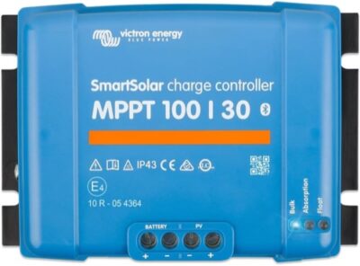
Victron SmartSolar 100/30 Review: Excellent Control for 30A Systems

A 30A charging job at 12V or 24V

Victron SmartSolar 100/30 Review: Excellent Control for 30A Systems

Check price at Amazon Jump to details
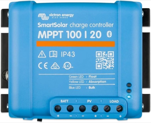
Victron SmartSolar 100/20 Review: Compact Control from 12V to 48V

Lower charge current with documented 48V support

Victron SmartSolar 100/20 Review: Compact Control from 12V to 48V

Check price at Amazon Jump to details

The best solar charge controller for LiFePO4 is the one that can work within the battery’s requirements, not merely the one with a lithium preset. This shortlist compares the SmartSolar 100/30 and the reviewed 100/20. Their different output-current and battery-voltage roles matter alongside settings, sensing and BMS behavior.

Begin With the Battery’s Charging Requirements

Obtain the battery manufacturer’s voltage targets, permitted charge current and temperature restrictions before selecting the controller. The battery chemistry name is only a starting point. A generic internet setting is not a substitute for the requirements of the actual battery and its BMS.

Identify how the system should behave when charging is not permitted. That includes low temperature and other conditions in which the BMS or a supported control arrangement limits charging. The controller and battery need a compatible plan rather than an assumption that one will always correct the other’s behavior.

The LiFePO4 settings guide helps organize the information to gather. Keep the final settings tied to the equipment documentation rather than copying them from a different bank that happens to use the same chemistry.

Choose Between Charge Current and Bank-Voltage Support

The SmartSolar 100/30 is the higher-output candidate on this two-product page for a compatible 12V or 24V bank. The reviewed 100/20 offers a lower-current route with documented 48V support. That distinction is more informative than treating the larger suffix as a universal upgrade.

Both choices still need an appropriate PV input design. A wider supported battery-voltage range does not imply a higher PV open-circuit voltage ceiling. Nor does it prove that an existing short string can operate correctly after the battery voltage changes.

Match the exact model and revision to the documentation. The detailed cards and product-owned tables preserve the distinction between bank-voltage support, solar-input restrictions and battery-side output. Do not merge those into a single power score.

Battery-side priority Comparison to make What remains separate
More charging current on a suitable 12V/24V bank The reviewed 100/30 role Battery acceptance and solar-input limits
A compatible lower-current bank, including a documented 48V option The reviewed 100/20 role PV starting conditions and string-voltage ceiling
Low-temperature charging restrictions Supported sensing and control arrangement A lithium preset alone

Specify Where Battery Temperature Comes From

A controller’s temperature and the battery’s temperature are not necessarily the same. They may be installed in different compartments or exposed to different conditions. Determine which temperature information the intended control function actually uses and what equipment is required to provide it.

For a supported external-sensing arrangement, check compatibility, configuration and behavior if the relevant information is not available. Do not assume that enabling a setting creates a battery temperature measurement. Include the required sensing equipment in both the design and the purchase budget.

Battery-integrated protection and controller-based control can have different roles. The battery documentation should establish what is permitted, while the system design explains how that requirement is met. This comparison is not a recommendation to bypass protection or experimentally charge outside the battery’s allowed conditions.

Temperature check: establish the source of the battery-temperature information and the device responsible for limiting charging. A menu label alone does not establish either.

Keep Configuration Separate From Routine BMS Protection

A properly configured controller should follow the battery’s intended charging requirements. The existence of a protective BMS does not make arbitrary charging settings acceptable. Repeated protective interruptions should prompt investigation of the system rather than being treated as the ordinary charging strategy.

Review any charging stages or functions that may not be appropriate for the chosen battery. Do not enable a lead-acid-oriented function simply because it appears in a controller’s menu. The correct profile depends on the battery’s explicit requirements and the supported controller configuration.

If the installation includes multiple charging sources, their combined behavior matters. A solar controller’s individual current setting is not automatically a limit on the total current entering the battery from every source. Resolve the full system arrangement before interpreting one device’s settings as complete protection.

Inspect the PV Side After the Battery Choice

Check the array against the selected controller’s input requirements at the chosen bank voltage. Higher-voltage battery systems can need a different panel arrangement to provide adequate operating headroom. Cold-corrected open-circuit voltage remains a separate ceiling check at the other end of the input window.

Use the controller’s documented PV power and current restrictions, including any conditions the manufacturer attaches. The battery’s acceptable charge current also remains a limit. Neither a capable BMS nor a large array changes the selected controller’s permitted operating envelope.

When the panel arrangement needs to change, use the string-layout guide to understand the questions involved. The final arrangement must follow the actual panel and controller documentation.

Record the Setup So It Can Be Checked Later

Keep a record of the exact battery model, controller revision, settings and sensing arrangement. This makes later troubleshooting more useful than relying on a screenshot from a previous installation or an undocumented claim that the lithium mode was selected.

During appropriate commissioning by a competent installer, compare intended behavior with the equipment’s indicated operation using the manufacturer’s procedures. Do not create unsafe conditions to test protection. If required behavior cannot be established, resolve that uncertainty before leaving the system unattended.

These two choices are supported by documentation and the research behind the linked reviews; Solar Power Picks is not claiming first-party battery testing. Other controllers may be suitable, but this is a deliberately limited shortlist, not a complete ranking of every lithium-capable product available.

  • Record the battery-specific settings and permitted charge current.
  • Identify the actual temperature-sensing and control arrangement.
  • Account for all charging sources.
  • Retain exact-model manuals and a configuration record.
A 30A charging job at 12V or 24V

Victron SmartSolar 100/30 Review: Excellent Control for 30A Systems

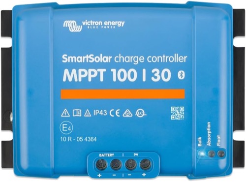
Victron SmartSolar 100/30 Review: Excellent Control for 30A Systems

Get it now:

Check latest price

What to know

  • Controller type: MPPT
  • Rated battery-side charge current: 30A
  • Supported battery-system voltage: 12V / 24V automatic selection
  • Maximum PV open-circuit voltage (Voc): 100V
  • App, communications, and data history: Built-in Bluetooth with VictronConnect; VE.Direct port

The SmartSolar 100/30 is the higher-output candidate here when the LiFePO4 bank is 12V or 24V and the array fits its limits. The value is a documented configuration workflow rather than the largest voltage label. Verify the battery maker's settings and supported temperature-sensing arrangement before enabling unattended charging.

BrandVictron Energy
Exact model / revision / ASINSmartSolar MPPT 100/30 (ASIN B073ZJ3L13)
Controller typeMPPT
Rated battery-side charge current30A
Supported battery-system voltage12V / 24V automatic selection
Battery chemistry and profile supportLead-acid and lithium via eight presets or a user-defined algorithm
Maximum PV open-circuit voltage (Voc)100V
Maximum PV short-circuit/input current (Isc)35A
Maximum PV power by battery voltage440W @ 12V; 880W @ 24V; 48V not supported
Minimum PV/start voltage requirementPV voltage must exceed battery voltage by 5V to start and by 1V to continue charging
Load output and low-voltage disconnectNo physical load terminals; virtual load output via VE.Direct
Grounding topologyIsolated chassis; positive or negative battery grounding permitted at one point; do not ground PV positive or negative
Charging stages and custom voltage controlAdaptive multi-stage; eight presets or user-defined
Temperature sensing and lithium low-temperature behaviorInternal sensor; external sensing and configurable low-temp cutoff via VE.Smart
Display and local controlsStatus LEDs; optional MPPT Control display
App, communications, and data historyBuilt-in Bluetooth with VictronConnect; VE.Direct port
Maximum terminal conductor size16 mm² / AWG 6
Controller self-consumption30mA at 12V; 20mA at 24V
Published tracking/conversion efficiency98%
Cooling method and thermal deratingNatural convection / passive cooling; full rated output through 40°C, then temperature-limited
Electrical protectionsPV reverse-polarity, output short-circuit, and overtemperature protection; no internal ground-fault protection
Enclosure, ingress rating, and operating temperatureIP43 electronics / IP22 terminals; -30°C to 60°C
CertificationsEN/IEC 62109-1, UL 1741, and CSA C22.2 No. 107.1-16
Dimensions, weight, and included accessories130 × 186 × 70 mm; 1.3 kg
Warranty5 years
Lower charge current with documented 48V support

Victron SmartSolar 100/20 Review: Compact Control from 12V to 48V

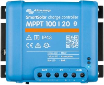
Victron SmartSolar 100/20 Review: Compact Control from 12V to 48V

Get it now:

Check latest price

What to know

  • Controller type: MPPT
  • Rated battery-side charge current: 20A
  • Supported battery-system voltage: 12V / 24V / 48V automatic selection
  • Maximum PV open-circuit voltage (Voc): 100V
  • App, communications, and data history: Built-in Bluetooth with VictronConnect; VE.Direct port

The reviewed SmartSolar 100/20 gives this shortlist a different bank-voltage option: documented 48V support with a 20A charge-current ceiling. That does not make its PV voltage window unlimited or turn it into the higher-output 100/30. Plan the battery-temperature information and control path explicitly, and match the delivered model to the reviewed documentation.

BrandVictron Energy
Exact model / revision / ASINSmartSolar MPPT 100/20 (ASIN B075NPQHQK)
Controller typeMPPT
Rated battery-side charge current20A
Supported battery-system voltage12V / 24V / 48V automatic selection
Battery chemistry and profile supportLead-acid and lithium via presets or a user-defined algorithm
Maximum PV open-circuit voltage (Voc)100V
Maximum PV short-circuit/input current (Isc)20A
Maximum PV power by battery voltage290W @ 12V; 580W @ 24V; 1,160W @ 48V
Minimum PV/start voltage requirementPV voltage must exceed battery voltage by 5V to start and by 1V to continue charging
Load output and low-voltage disconnect20A @ 12V/24V; 1A @ 48V, with BatteryLife and configurable control
Grounding topologyIsolated chassis; positive or negative battery grounding permitted at one point; do not ground PV positive or negative
Charging stages and custom voltage controlAdaptive multi-stage or user-defined algorithm
Temperature sensing and lithium low-temperature behaviorInternal compensation; configurable low-temperature cutoff and optional VE.Smart battery sensing
Display and local controlsStatus LEDs; detailed control through VictronConnect
App, communications, and data historyBuilt-in Bluetooth with VictronConnect; VE.Direct port
Maximum terminal conductor size6 mm² / AWG 10
Controller self-consumption25mA at 12V; 15mA at 24V or 48V
Published tracking/conversion efficiency98% peak
Cooling method and thermal deratingNatural convection / passive cooling; full rated output through 40°C, then temperature-limited
Electrical protectionsPV reverse-polarity, output short-circuit, and overtemperature protection; no internal ground-fault protection
Enclosure, ingress rating, and operating temperatureIP43 electronics / IP22 terminals; -30°C to 60°C
CertificationsEN/IEC 62109-1, UL 1741, and CSA C22.2 No. 107.1-16
Dimensions, weight, and included accessories100 × 131 × 60 mm; 0.65 kg
Warranty5 years

Product Comparison

Feature Victron SmartSolar 100/30 Review: Excellent Control for 30A Systems Victron SmartSolar 100/20 Review: Compact Control from 12V to 48V
Product Image
Victron SmartSolar 100/30 Review: Excellent Control for 30A Systems
Victron SmartSolar 100/20 Review: Compact Control from 12V to 48V
Price $121.13 $82.79
Rating
4.6 / 5
4.5 / 5
Category Solar Charge Controllers Solar Charge Controllers
Brand Victron Energy Victron Energy
Exact model / revision / ASIN SmartSolar MPPT 100/30 (ASIN B073ZJ3L13) SmartSolar MPPT 100/20 (ASIN B075NPQHQK)
Controller type MPPT MPPT
Rated battery-side charge current 30A 20A
Supported battery-system voltage 12V / 24V automatic selection 12V / 24V / 48V automatic selection
Battery chemistry and profile support Lead-acid and lithium via eight presets or a user-defined algorithm Lead-acid and lithium via presets or a user-defined algorithm
Maximum PV open-circuit voltage (Voc) 100V 100V
Maximum PV short-circuit/input current (Isc) 35A 20A
Maximum PV power by battery voltage 440W @ 12V; 880W @ 24V; 48V not supported 290W @ 12V; 580W @ 24V; 1,160W @ 48V
Minimum PV/start voltage requirement PV voltage must exceed battery voltage by 5V to start and by 1V to continue charging PV voltage must exceed battery voltage by 5V to start and by 1V to continue charging
Load output and low-voltage disconnect No physical load terminals; virtual load output via VE.Direct 20A @ 12V/24V; 1A @ 48V, with BatteryLife and configurable control
Grounding topology Isolated chassis; positive or negative battery grounding permitted at one point; do not ground PV positive or negative Isolated chassis; positive or negative battery grounding permitted at one point; do not ground PV positive or negative
Charging stages and custom voltage control Adaptive multi-stage; eight presets or user-defined Adaptive multi-stage or user-defined algorithm
Temperature sensing and lithium low-temperature behavior Internal sensor; external sensing and configurable low-temp cutoff via VE.Smart Internal compensation; configurable low-temperature cutoff and optional VE.Smart battery sensing
Display and local controls Status LEDs; optional MPPT Control display Status LEDs; detailed control through VictronConnect
App, communications, and data history Built-in Bluetooth with VictronConnect; VE.Direct port Built-in Bluetooth with VictronConnect; VE.Direct port
Maximum terminal conductor size 16 mm² / AWG 6 6 mm² / AWG 10
Controller self-consumption 30mA at 12V; 20mA at 24V 25mA at 12V; 15mA at 24V or 48V
Published tracking/conversion efficiency 98% 98% peak
Cooling method and thermal derating Natural convection / passive cooling; full rated output through 40°C, then temperature-limited Natural convection / passive cooling; full rated output through 40°C, then temperature-limited
Electrical protections PV reverse-polarity, output short-circuit, and overtemperature protection; no internal ground-fault protection PV reverse-polarity, output short-circuit, and overtemperature protection; no internal ground-fault protection
Enclosure, ingress rating, and operating temperature IP43 electronics / IP22 terminals; -30°C to 60°C IP43 electronics / IP22 terminals; -30°C to 60°C
Certifications EN/IEC 62109-1, UL 1741, and CSA C22.2 No. 107.1-16 EN/IEC 62109-1, UL 1741, and CSA C22.2 No. 107.1-16
Dimensions, weight, and included accessories 130 × 186 × 70 mm; 1.3 kg 100 × 131 × 60 mm; 0.65 kg
Warranty 5 years 5 years
Buy Now View Deal View Deal

A Suitable Lithium Controller Is Part of a Complete Charging Plan

Compare SmartSolar 100/30 for its 12V/24V, higher-current role with the reviewed 100/20 for a lower-current option that includes documented 48V support. Neither eliminates the need for correct battery settings, temperature information and input checks. Select the complete compatible arrangement, including any required sensing hardware.

Frequently Asked Questions

Why does this LiFePO4 shortlist contain only two controllers?

The page is deliberately limited to the candidates retained after the current evidence and product-identity review. That does not mean only two suitable controllers exist. A shorter list avoids treating unresolved documentation or a mismatched seller destination as an approved recommendation.

Is the 100/30 always preferable to the 100/20 for lithium?

No. The reviewed models have different current and bank-voltage roles. A higher current rating is useful only when the array and battery can use it, while the required bank voltage may decide the choice first. Compare the exact specifications, not the suffix alone.

Does a lithium preset include battery temperature measurement?

Not necessarily. A preset defines part of the charging configuration; it does not establish where battery temperature is measured or which supported protection arrangement is present. Check the exact controller, sensing hardware and battery requirements as a complete system.

Can the battery BMS replace correct controller settings?

No. Protective behavior is not a reason to use inappropriate charging settings. Configure the controller according to the battery requirements and supported system design. Repeated BMS interruptions should be investigated rather than assumed to be normal charge regulation.

Can I reuse my array after changing to a higher-voltage battery bank?

Only if the array still meets the selected controller’s starting, operating and maximum-input requirements for that bank. The change can affect the required panel arrangement and usable power allowance. Check actual module data rather than assuming the old wiring remains appropriate.

What should I keep in the lithium commissioning record?

Record the battery and controller identities, relevant charging limits, selected settings, sensing hardware and the intended role of other charging sources. Keep the manuals with that record. It should explain the configuration without requiring somebody else to guess why a value was selected.

×

About Solar Power Picks

Portable Solar Power, Backup Power, and Off-Grid Gear Guides

Your trusted source for honest, in-depth product reviews and comparisons.

Quick Links

  • Best Picks
  • Reviews
  • Guides
  • Comparisons
  • Calculator
  • Privacy policy
  • Favorites

Categories

  • Portable Power Stations
  • Solar Batteries
  • Solar Battery Maintainers
  • Solar Charge Controllers
  • Solar Generators
  • Solar Panels

© 2026 Solar Power Picks. All Rights Reserved.

We may earn a commission when you purchase through links on our site. Learn more