Victron SmartSolar 100/50 Review: 50A Is Powerful, 100V Is the Catch
At a Glance
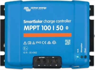
KEY FEATURES
- Controller: MPPT; 50A rated charge output.
- System: 12V / 24V automatic; Lead-acid and lithium through presets or user-defined algorithm.
- PV boundary: 100V maximum Voc; 700W @ 12V; 1,400W @ 24V maximum PV power.
- Controls: Status LEDs; optional external display; Built-in Bluetooth with VictronConnect; VE.Direct.
- Best fit: Large 12V/24V LiFePO4 or lead-acid systems needing 50A charging and built-in Bluetooth.
PROS
- 50A MPPT output and strong VictronConnect tools suit substantial 12V or 24V arrays.
- Owner evidence repeatedly supports useful harvest, quiet operation, and clear history.
- A 24V design can use the controller's power envelope with more manageable current.
CONS
- The 100V absolute PV ceiling can rule out convenient series strings after cold correction.
- Sustained high current demands careful conductor fit, torque, airflow, and temperature checks.
- Battery-level sensing and wider ecosystem integration can add hardware cost.
Editor's Choice
Editorial assessment based on exact-model documentation and qualitative exact-ASIN owner evidence; no first-party bench test or population-rate claim
Price and availability subject to change
Will the Victron SmartSolar 100/50 Fit Your Solar Array?
Estimate required charging current and check it against the documented limits for Victron SmartSolar 100/50.
Solar Charge Controller Size Calculator
What size charge controller do I need?
The Victron SmartSolar 100/50 delivers 50A of passively cooled MPPT charging, built-in Bluetooth, a published 60A array Isc limit, user-defined battery control, and a five-year warranty. For a 12V or 24V cabin, RV, or boat system, it is one of the better-documented controllers in this current class.
Its name also exposes the main tradeoff. The controller accepts no more than 100V PV open circuit and does not support a 48V battery. Buyers attracted to 50A output can discover that series-string voltage—not current—is the first limit they hit, especially with modern high-Voc panels or cold climates.
| Best For | Defining Advantage | Deciding Constraint | Evidence Confidence |
|---|---|---|---|
| 700W-class 12V or 1,400W-class 24V systems valuing app control | 50A output with complete PV-current documentation | 100V ceiling and no 48V battery support | High for specifications; medium-high for owner experience |
The 100/50 Rewards a 24V Design but Punishes Casual String Sizing
The expanded owner record supports the SmartSolar 100/50 as a mature mid-size controller with strong app visibility and useful real-world output. It also shows why many successful installations are built around 24V rather than treating 50A as a reason to stay at 12V. Raising battery voltage can reduce current for the same system power, but it changes battery configuration, inverter choice, DC loads, and protection. It is a system decision, not a controller setting.
Several detailed accounts discuss substantial arrays, near-full output, quiet operation, and VictronConnect history. Others mention terminal fit, heat at sustained current, isolated failures, or support that depends on the seller. Those reports identify acceptance tests: confirm the authorized sales path, preserve the serial and order record, torque conductors correctly, and log temperature and output during a long high-sun charge.
Bluetooth history is valuable for comparing harvest across days, yet it is not revenue-grade metering or a substitute for a shunt when battery accounting matters. External battery temperature and voltage sensing also require compatible additional hardware and configuration. Plan those ecosystem pieces before judging the controller’s total price.
The 100/50 is strongest for a carefully calculated 12V or 24V array whose string voltage has comfortable margin below 100V. Buyers who need longer series strings should not “test” the voltage ceiling; the 150V family is the proper design route.
The Best Electrical Fit Is Often 24V
Victron publishes 700W nominal PV power at 12V and 1,400W at 24V. Both rows share the same 50A output, 100V Voc ceiling, and 60A PV short-circuit-current limit. Moving from 12V to 24V allows twice the panel power at the same battery-side current class and can reduce current elsewhere in the system.
One owner reconfigured four batteries from 12V parallel to a 24V 2S2P bank, citing lower current and better conductor fit. The same owner used six 200W panels in 3S2P and described the controller reaching full output. That is a useful real-system example, not a universal endorsement of the string: every module and climate produces a different cold Voc.
| Limit | 12V Bank | 24V Bank | Planning Implication |
|---|---|---|---|
| Rated charge output | 50A | 50A | Battery and cable current remain substantial |
| Nominal PV allowance | 700W | 1,400W | 24V makes fuller use of the 50A class |
| Maximum PV Voc | 100V | 100V | Series length does not increase with bank voltage |
| Maximum array Isc | 60A | 60A | Parallel strings must remain within a documented limit |
| Battery compatibility | Supported | Supported | 48V is not supported at all |
The controller starts only when PV voltage is sufficiently above battery voltage, and operating headroom must remain under changing conditions. Use the current manual’s startup and continuation requirements as well as the absolute ceiling. A string that is safe at noon in summer can exceed 100V on a clear freezing morning.
Sizing priority — Check cold Voc before celebrating the 60A Isc allowance. A generous current ceiling cannot rescue a series string that exceeds 100V.
A Detailed Owner Comparison Adds Useful—but Limited—Context
One owner compared the Victron 100/50 with 40A AMPINVT and EPEVER controllers using four 300W panels, a 12V 280Ah LiFePO4 battery, and BMS current as a common external reading. The tests covered series/parallel arrangements, cloud, shade, and full sun and were repeated several times.
The reviewer observed faster initial tracking from AMPINVT but oscillating current, slightly stronger Victron results in some cloudy or shaded configurations, and higher full-sun output from Victron because it alone was rated 50A. The owner explicitly warned that different current ratings, batches, setups, and conditions prevented an absolute ranking and that the experiment said nothing about longevity.
That caution is correct. The comparison is valuable because it documents equipment and method, but it is not a controlled irradiance laboratory. The fair takeaway is that the Victron behaved competitively and used its higher current headroom—not that one small test proves a universal efficiency percentage.
| Comparative Observation | What It Supports | What It Cannot Prove |
|---|---|---|
| BMS used as common current reference | Reduced reliance on each controller’s display calibration | BMS accuracy and synchronized irradiance were not independently verified |
| Repeated cloud/shade configurations | More useful than a single snapshot | All possible shading layouts or algorithms |
| Victron produced more at full sun | 50A unit had output headroom over 40A units | Equal-class conversion superiority |
| AMPINVT tracked fast but varied | A real behavior in that system | Behavior of every unit or firmware version |
| Reviewer disclosed limitations | Increases evidentiary value | Does not turn owner testing into certification |
Why the 100V Ceiling Can Force a Different Model
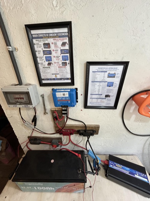
At 50A, buyers often pair the controller with several large panels. Many modern modules have Voc around the 40V–50V range before cold correction. Two in series may fit while three do not; the exact result depends on the datasheet and design temperature.
Parallel wiring can keep voltage lower, but it increases PV current and may require string fusing, larger conductors, and more connectors. The 60A Isc publication makes that design possible to evaluate; it does not make unlimited parallel input acceptable.
| Array Pressure | 100/50 Response | Better Direction If It Fails |
|---|---|---|
| Need three high-Voc modules in series | Often constrained by 100V | Choose an appropriate 150V/250V Victron model |
| Long roof-to-controller cable | Higher current may increase loss | Raise safe string voltage with a higher-Voc controller |
| Many parallel strings | 60A Isc provides a clear boundary | Reconfigure series/parallel layout or split across controllers |
| Planned 48V battery conversion | Unsupported | Select a 48V-capable SmartSolar model now |
| Fixed 24V bank around 1.2–1.4kW | Strong potential fit | Verify cold Voc and battery charge acceptance |
One owner concluded that a 150/60 would have provided better future flexibility after building a 24V, 1,200W system. Another returned a 100/50 because an existing 100/30 still met the actual need. Both illustrate good selection discipline: more current is valuable only when the array and bank can use it.
VictronConnect Becomes the 100/50 Control Panel
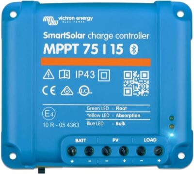
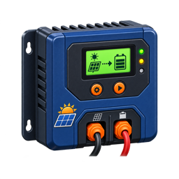
There is no numeric front display. Status LEDs provide basic state information; detailed readings and settings live in VictronConnect or compatible external hardware. Bluetooth is built in, and owners repeatedly praised pairing, real-time data, custom profiles, and 30-day history.
One owner already using a SmartShunt described a smooth move from a difficult PowMr setup to the Victron ecosystem. Another monitored the open Bluetooth data with a Raspberry Pi while using Victron software for control. A further reviewer preferred the newer Windows app because the phone display felt cramped.
The app is strong but local-range. Remote internet access requires a GX-class system or other supported hardware. Record the PIN labels and settings before final installation. A phone-free user may prefer a controller with a physical LCD or budget for an external display.
Interface decision — Built-in Bluetooth removes a dongle, not the need to choose a monitoring architecture. Decide whether you need local phone access, a permanent display, open-data integration, or true off-site monitoring.
Battery Sensing and Cold-Charge Protection Need the Right Hardware
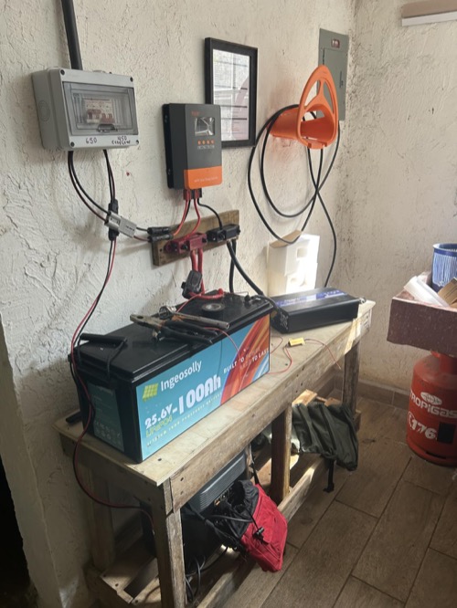
The 100/50 supports adaptive presets and a user-defined algorithm for lead-acid and lithium batteries. Internal sensing is standard. Compatible VE.Smart battery voltage and temperature sensing can improve information at the battery and enables configurable low-temperature behavior in a supported system.
One RV owner bought a separate Victron temperature/voltage sensor because the batteries sat on the ground while the controller was inside. That is a sensible response to spatial temperature differences. Another owner assumed the controller lacked temperature sensing entirely; the more precise statement is that battery-level external data requires compatible additional sensing.
For LiFePO4, match charge voltage, maximum current, float policy, and low-temperature threshold to the exact battery/BMS manual. For lead-acid, confirm temperature compensation and sensor placement. Do not infer the battery’s state or temperature solely from controller-enclosure measurements.
| Battery Requirement | 100/50 Capability | Verification Needed |
|---|---|---|
| Preset charging | Common profiles | Exact preset values versus battery manual |
| Custom algorithm | User-defined values | Avoid accidental equalization or excessive voltage |
| Remote battery voltage | Compatible VE.Smart sensing | Product compatibility and network setup |
| Battery temperature | Compatible external sensing | Sensor placement and configured response |
| LiFePO4 cold cutoff | Configurable in supported sensing setup | Prove which device actually blocks charging |
Passive Cooling Is Quiet, Not Permission to Enclose It
The controller uses passive cooling and is rated at 98% peak efficiency. It measures about 130 × 186 × 70 mm and weighs 1.3kg. Owners described silent operation and generally reasonable temperature, though load, ambient heat, and airflow differ.
Victron rates the electronics IP43 and the terminal area IP22. It needs a dry protected location, correct vertical orientation, and manual-specified clearance. Do not interpret an owner’s “outdoor” or boat use as proof that exposed terminals tolerate weather.
Terminals accept up to 16mm² / AWG 6 according to the normalized specification. One detailed comparison owner said 4 AWG would not fit; another European owner reported 16mm² fitting securely. These accounts align with the published maximum. Size the circuit first and verify that the chosen conductor terminates without strand removal.
No Physical Load Output Means Cleaner Boundaries
The 100/50 has no physical load terminals. Large inverters and DC distribution connect to a protected battery bus. Virtual load control can be implemented through VE.Direct and suitable external hardware, but it is a control architecture rather than a 50A accessory outlet.
This absence can be an advantage in larger systems: it discourages routing high-current loads through the controller. Buyers needing built-in dusk lighting or direct low-voltage disconnect should compare the Rover line or plan external battery protection and switching.
It also clarifies failure domains. The controller can charge while a separate battery monitor, inverter, and distribution system handle consumption. That modular approach costs more hardware, but service and protection can be designed around each circuit instead of depending on one controller output for unrelated loads.
100/50 Design Checklist
- Confirm that the battery remains 12V or 24V for the controller’s service life.
- Calculate every string’s cold-corrected Voc below 100V.
- Add parallel-string Isc and stay within 60A plus required design rules.
- Use the 700W or 1,400W row for the actual bank.
- Verify the battery accepts up to 50A or configure a lower limit.
- Decide whether VictronConnect alone meets local/remote monitoring needs.
- Add compatible battery sensing when temperature or voltage drop requires it.
- Size conductors and protection; confirm AWG 6 / 16mm² terminal fit.
- Provide protected IP22/IP43 mounting and passive-cooling clearance.
- Connect inverters and distribution to a properly protected battery bus.
Pros & Cons Analysis
Based on documented specifications and owner feedback
Pros
- 50A — 50A MPPT output.
- Built-in — Built-in Bluetooth.
- Published — Published 60A PV Isc limit.
- Five-year — Five-year warranty.
Cons
- Check: 12V/24V only.
- Check: No physical load terminals.
- Check: No numeric front display.
- Check: Protected mounting required.
Bottom Line: Premium 50A Control for the Right Voltage Window
Verdict: The Victron SmartSolar 100/50 combines strong documentation, a useful 60A PV Isc limit, built-in Bluetooth, passive cooling, flexible charging, and a five-year warranty. Within a carefully calculated 12V/24V array, it is one of the safest recommendations in the cluster.
Best reason to buy: You need up to 50A and value exact electrical limits, VictronConnect, and long warranty support more than a local screen.
Reason to pause: The 100V input and lack of 48V battery support can block expansion sooner than the 50A rating suggests. Calculate the future string and bank, not only today's array.
Frequently Asked Questions
Is the Victron Energy SmartSolar 100/50 MPPT or PWM?
The exact model is documented as MPPT. That topology does not replace checks of PV voltage, input current, output current, and battery compatibility.
What battery voltage does the Victron Energy SmartSolar 100/50 support?
12V / 24V automatic. Confirm detection and selection behavior in the current exact-model manual.
What is the maximum PV voltage?
100V. Use cold-corrected array Voc rather than the panel's warm-day value.
How much solar can it handle?
700W @ 12V; 1,400W @ 24V. The PV voltage, PV current, and battery-side charge-current limits must all be satisfied at the same time.
Does the Victron Energy SmartSolar 100/50 work with lithium batteries?
Lead-acid and lithium through presets or user-defined algorithm. Match every charging value and low-temperature strategy to the battery documentation.
Does it include app monitoring?
Built-in Bluetooth with VictronConnect; VE.Direct. Verify whether any required accessory is included in the exact bundle.
Can I connect an inverter to its load terminals?
Normally no. High-current and surge loads should use a correctly fused battery-side connection unless the controller manual explicitly permits the planned load.
Who should buy the Victron Energy SmartSolar 100/50?
Large 12V/24V LiFePO4 or lead-acid systems needing 50A charging and built-in Bluetooth.
Technical Specifications
| Brand | Victron Energy |
|---|---|
| Exact model / revision / ASIN | SmartSolar MPPT 100/50 (ASIN B073ZJ43L1) |
| Controller type | MPPT |
| Rated battery-side charge current | 50A |
| Supported battery-system voltage | 12V / 24V automatic |
| Battery chemistry and profile support | Lead-acid and lithium through presets or user-defined algorithm |
| Maximum PV open-circuit voltage (Voc) | 100V |
| Maximum PV short-circuit/input current (Isc) | 60A |
| Maximum PV power by battery voltage | 700W @ 12V; 1,400W @ 24V |
| Minimum PV/start voltage requirement | PV voltage must exceed battery voltage by 5V to start and by 1V to continue charging |
| Load output and low-voltage disconnect | No physical load terminals; virtual load control through VE.Direct |
| Grounding topology | Isolated chassis; positive or negative battery grounding permitted at one point; do not ground PV positive or negative |
| Charging stages and custom voltage control | Adaptive multi-stage; presets and user-defined settings |
| Temperature sensing and lithium low-temperature behavior | Internal sensing; external sensing and configurable lithium low-temp cutoff through VE.Smart |
| Display and local controls | Status LEDs; optional external display |
| App, communications, and data history | Built-in Bluetooth with VictronConnect; VE.Direct |
| Maximum terminal conductor size | 16 mm² / AWG 6 |
| Controller self-consumption | 30mA at 12V; 20mA at 24V |
| Published tracking/conversion efficiency | 98% |
| Cooling method and thermal derating | Natural convection / passive cooling; full rated output through 40°C, then temperature-limited |
| Electrical protections | PV reverse-polarity, output short-circuit, and overtemperature protection; no internal ground-fault protection |
| Enclosure, ingress rating, and operating temperature | IP43 electronics / IP22 terminals; -30°C to 60°C |
| Certifications | EN/IEC 62109-1, UL 1741, and CSA C22.2 No. 107.1-16 |
| Dimensions, weight, and included accessories | 130 × 186 × 70 mm; 1.3 kg |
| Warranty | 5 years |