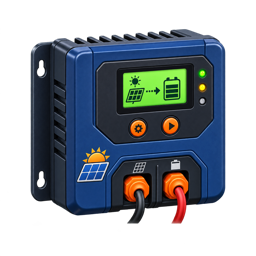
ECO-WORTHY 12A Boost MPPT Review: A Specialist, Not a Normal Controller
At a Glance
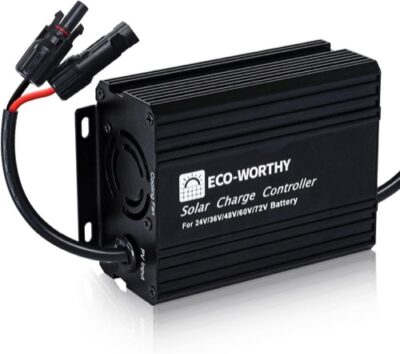
KEY FEATURES
- Controller: Boost MPPT; 12A rated charge output.
- System: 24V / 36V / 48V / 60V / 72V battery output; Lead-acid and lithium configurations; verify exact voltage profile.
- PV boundary: 24V nominal input; reviewed page describes 12V/24V panel compatibility maximum Voc; 216W with 12V-class input; 432W with 24V-class input maximum PV power.
- Controls: LCD and buttons; No app or communications port.
- Best fit: Charging 24V-72V battery banks from a lower-voltage 12V or 24V solar array.
PROS
- Boost topology can charge higher-voltage banks from lower-voltage solar panels.
- Useful niche fit for golf carts, boat lifts, e-bikes, and selected 48V systems.
- Adjustable output targets provide more flexibility than a fixed-voltage maintainer.
CONS
- Boost-only operation is easy to confuse with conventional buck MPPT charging.
- Connection order, battery target voltage, fusing, and conductor sizing are critical.
- Documentation and support feedback are inconsistent; commissioning needs independent measurements.
Editor's Choice
Editorial assessment based on exact-model documentation and qualitative exact-ASIN owner evidence; no first-party bench test or population-rate claim
Will the ECO-WORTHY 12A Boost MPPT Fit Your Solar Array?
Estimate required charging current and check it against the documented limits for ECO-WORTHY 12A Boost MPPT.
Solar Charge Controller Size Calculator
What size charge controller do I need?
The ECO-WORTHY 12A Boost MPPT solves a problem most solar controllers cannot: it raises a lower PV voltage to charge a higher-voltage battery. That makes a 12V- or 24V-class array potentially useful with 24V, 36V, 48V, 60V, or 72V battery systems used in golf carts, e-bikes, boat lifts, and other specialized installations.
That same architecture makes it easy to buy incorrectly. This is not a conventional buck MPPT for charging a 12V battery from a higher-voltage array. The reviewed listing explicitly says panel operating voltage must be lower than battery voltage. Published input current, terminal size, enclosure rating, operating temperature, and warranty were not available in the supplied evidence, so the article cannot responsibly treat it as a universal bargain controller.
| Best For | Unique Capability | Main Risk | Evidence Confidence |
|---|---|---|---|
| Adding low-voltage PV to a 24V–72V battery system | Boost conversion raises PV voltage | Reversing the expected voltage relationship or undersizing PV wiring | Medium; the use case is clear, but several installation limits remain unpublished |
Boost-Only Architecture Makes Connection Order Part of the Design
The expanded exact-ASIN record confirms that this ECO-WORTHY model solves a real but uncommon problem: using a lower-voltage solar source to charge a higher-voltage battery bank. Owners describe golf carts, boat lifts, e-bikes, cabins, and 48V systems where conventional buck MPPT controllers are electrically the wrong direction. The same accounts make clear that it is boost-only, not a universal buck-boost controller.
Connection order deserves unusual attention because owner instructions repeatedly describe the PV source waking the controller before the battery connection. Follow the current exact manual supplied with the delivered unit rather than importing the battery-first sequence used by many ordinary controllers. Before connecting, set the voltage range and charge target from the battery maker’s limits. A 48V label does not define the correct absorption or termination voltage for every chemistry.
| Boost-system check | Required value | Failure prevented |
|---|---|---|
| PV source | Operating voltage, cold Voc, current, and available watts | No startup, input over-voltage, or unrealistic output expectation |
| Battery | Series count, chemistry, BMS limit, target voltage | Undercharge, overcharge, or BMS shutdown |
| Conductors | Input and output current, length, fuse, temperature | Voltage drop, heating, smoke, or damaged terminals |
| Commissioning | Exact connection order and measured current | Misdiagnosing a topology or setup error as a dead unit |
Owner reports include both useful charging and serious fault symptoms. That mix makes conservative conductors, correctly placed protection, and temperature checks mandatory during the return window. Do not infer 12A output from one operating snapshot: battery voltage, PV power, conversion loss, and the controller’s thermal state determine actual current. If the system can use a conventional higher-voltage PV string and buck MPPT controller, compare that simpler architecture before choosing boost conversion.
Start with the Direction of Conversion
Most familiar MPPT controllers accept a PV operating voltage above the battery and convert it downward. This ECO-WORTHY model works in the other direction. The solar input must operate below the selected battery charge voltage, and the electronics raise it to the bank’s required level.
That difference is not a minor setting. Connecting a conventional high-voltage string because “MPPT accepts extra voltage” misunderstands the product. Before purchase, write down the panel’s Voc, Vmp, Isc, and Imp; the battery’s nominal and maximum charge voltage; and the controller’s allowed input and output windows. If the exact manual does not confirm the combination, stop.
| Question | Boost Controller Answer | Conventional Buck MPPT Answer |
|---|---|---|
| Typical PV-to-battery voltage relationship | PV operating voltage lower than battery charge voltage | PV operating voltage higher than battery charge voltage |
| Example application | 12V/24V-class panel charging a 48V bank | Higher-voltage array charging a 12V/24V bank |
| Main selection mistake | Feeding an incompatible high PV voltage or expecting 12V battery support | Exceeding cold PV Voc or falling below the MPPT window |
| Current consequence | Lower input voltage can require substantial PV-side current | Higher PV voltage can reduce array-side current for equal power |
| Suitable substitute | Another documented boost controller | Not interchangeable solely because both say MPPT |
The controller is advertised for 24V, 36V, 48V, 60V, and 72V battery outputs. A buyer trying to charge an ordinary 12V bank should choose a conventional controller instead. A buyer with a 48V bank and only a small portable panel may have exactly the problem this product addresses.
Compatibility rule — Confirm the voltage relationship using operating voltages, not just nominal labels. “12V panel” and “48V battery” are shorthand; their datasheets contain the actual Vmp, Voc, charging, and cutoff values that govern the design.
What 12A Means at Higher Battery Voltage
ECO-WORTHY describes a 12A charge-output ceiling and maximum panel power of 216W with 12V-class input or 432W with 24V-class input. Output power is not simply the input current multiplied by the battery label: conversion loss, the actual PV operating point, controller limits, and battery charge voltage all matter.
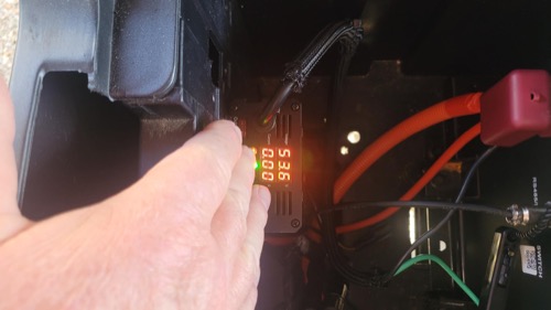
The listing claims up to 95% tracking efficiency and 93% peak conversion efficiency. Those are manufacturer figures, not independent measurements in the supplied evidence. A owner did provide a useful operating snapshot: one large panel produced about 36V at 9A, while the controller displayed roughly 52V at 4.7A into a 48V lithium battery. The user limited charging to 55V. That anecdote demonstrates boost behavior, but meter accuracy and test conditions were not independently checked.
| Reviewed Electrical Value | Published or Reported Figure | Planning Meaning |
|---|---|---|
| Rated output current | 12A | Battery-side current must remain within the bank’s limit |
| Supported battery voltages | 24V / 36V / 48V / 60V / 72V | No ordinary 12V-battery mode is documented |
| PV allowance with 12V-class input | 216W | Low input voltage can mean high array-side current |
| PV allowance with 24V-class input | 432W | Still verify actual Vmp/Voc and the controller window |
| Claimed tracking / conversion efficiency | 95% / 93% peak | Treat as listing claims, not guaranteed field output |
| Maximum PV current | Not published in reviewed evidence | Obtain the exact limit before final conductor and array design |
The Smoking-Wire Review Is a Design Warning
The most consequential supplied report came from an owner who initially struggled with voltage and a PV-line short. After correcting the setup, the controller boosted into a 48V system—but the PV wires became hot and reportedly smoked as input increased. The owner attributed the issue to needing larger conductors and remained positive about the controller.
That story should not be read as a successful stress test. Smoke means the circuit was unsafe. Boost conversion can draw comparatively high current on the lower-voltage side, so PV conductor ampacity, voltage drop, connection quality, fusing, and the controller’s unpublished input-current boundary deserve particular attention. A protection feature that prevents immediate controller damage does not make undersized wiring acceptable.
| Possible Cause of Heating | Required Check | Why Guessing Is Unsafe |
|---|---|---|
| Undersized PV conductors | Calculate ampacity and voltage drop for maximum expected input current | Low-voltage, high-current runs can lose substantial power as heat |
| Loose or damaged termination | Inspect and torque using the exact terminal specification | Resistance at one connection can create localized heating |
| Short or insulation fault | Isolate and test the complete circuit before energizing | Controller protection is not a substitute for fault correction |
| Array beyond input rating | Obtain PV-current and voltage limits from current documentation | The reviewed evidence omits the exact maximum input current |
| Inadequate overcurrent protection | Design fuses/breakers and disconnects for the actual conductors and sources | A battery-backed fault can deliver destructive current |
Safety stop — Hot insulation, odor, discoloration, arcing, or smoke requires immediate safe de-energization and fault correction. Do not increase wire size by trial and error while leaving the underlying current, terminal, and protection limits unresolved.
Where Owners Put the Boost Architecture to Work
One fifth-wheel owner used two of these controllers to add several hundred watts of lower-voltage panels to a 48V, 600Ah battery system whose primary inverters otherwise required much higher string voltage. One array used three 130W ECO-WORTHY panels and another used four 100W Renogy panels. The owner also considered a lightweight solar trailer for a 48V e-bike.
A boat-lift owner used a large 12V-class panel to maintain a 24V battery system and emphasized the unusual connection sequence. Another cabin owner said a single panel replenished more than a weekend’s energy over a month of absence. These are exactly the situations in which extra low-voltage PV is available but rebuilding the main array is inconvenient.
The applications remain anecdotes. The fifth-wheel report does not publish every module electrical value, and the cabin report does not quantify energy. They show plausible fit, not a pre-approved wiring diagram.
| Use Case | Fit | Deciding Requirement | Common Wrong Assumption |
|---|---|---|---|
| Portable panels supplementing a 48V RV bank | Strong | PV operating voltage below bank charge voltage and input current within limits | Any 400W array is automatically compatible |
| 12V-class panel maintaining a 24V boat-lift bank | Strong | Correct connection order, protected wiring, and suitable battery profile | A normal PWM controller can raise voltage |
| Solar charging a 48V e-bike pack | Conditional | Battery/BMS accepts the adjustable charge profile safely | Nominal 48V defines the correct maximum charge voltage |
| 60V or 72V mobility bank | Conditional | Exact controller range and battery maker requirements are documented | Selecting the nominal voltage completes configuration |
| Standard 12V RV house battery | Wrong tool | Controller does not document a 12V battery output mode | “12V panel compatible” means “12V battery compatible” |
| High-voltage residential series string | Wrong tool | Input is intended to remain below battery voltage | MPPT topology makes input direction irrelevant |
Connection Order Is Unusual and Important
Two owners specifically said the panel powers the controller and should be connected before the battery, unlike the battery-first sequence common to many conventional products. One stated that connecting in the other order prevented operation. This is a product-specific instruction that must be checked against the current manual rather than generalized to other controllers.
Before connection, isolate both sources, confirm polarity, measure PV open-circuit voltage with suitable equipment, and verify battery voltage and profile. Follow the exact sequence, then set the charge ceiling to the battery manufacturer’s requirement. The controller’s adjustable display does not know the battery’s safe values automatically.
| Commissioning Stage | ECO-WORTHY-Specific Check | Evidence to Keep |
|---|---|---|
| Identify equipment | Exact controller revision, panel datasheet, battery/BMS manual | Photos of labels and current manuals |
| Calculate | PV Vmp/Voc/current, output voltage/current, conductor drop | Written design sheet rather than nominal labels |
| Protect | Source disconnects, fusing, conductor ampacity, terminal capacity | Component ratings and installation diagram |
| Energize | Follow exact panel/battery connection order | Manual page and measured pre-connection voltages |
| Configure | Select nominal bank and maker-approved charge ceiling | Saved parameter list |
| Verify | Compare controller display with appropriate independent measurements | Initial and full-sun readings, including conductor temperature |
Battery Settings Require More Than Selecting 48V
The reviewed material lists lead-acid, lithium, gel, and flooded configurations. It does not provide enough evidence to publish one “correct” voltage for every 24V–72V bank. Series cell count, chemistry, BMS limits, balance behavior, charge current, and desired longevity all change the target.
No external temperature sensor or low-temperature lithium cutoff was documented. A lithium installation that can freeze therefore needs a battery/BMS strategy that actually blocks charging below the maker’s threshold. Lead-acid users must also confirm absorption, float, and any equalization behavior rather than assuming the nominal voltage selection supplies an ideal profile.
There are no documented load terminals or app communications. The LCD gives local voltage and current information and permits parameter adjustment, but an unattended installation may need separate battery monitoring. A screen value is a diagnostic clue, not an independent validation of the system.
Reliability Evidence Is Too Small for Certainty
That negative account matters because it describes the core function, but one person’s two units cannot establish a population-wide defect rate. Conversely, six positive reviews cannot prove long service life. The more defensible conclusion is that the design can solve a real voltage problem, while documentation gaps and sparse long-term evidence increase the burden on commissioning and monitoring.
Pros & Cons Analysis
Based on documented specifications and owner feedback
Pros
- Boosts — Boosts lower PV voltage to higher battery voltage.
- Supports — Supports 24V-72V batteries.
- Compact — Compact LCD controller.
- Useful — Useful specialized applications.
Cons
- Check: 12A output ceiling.
- Check: Not for ordinary 12V battery charging.
- Check: No app connection.
- Check: Sparse terminal and enclosure specifications.
Bottom Line: Valuable Only When You Need Voltage Boost
Verdict: The ECO-WORTHY 12A Boost MPPT is compelling for a narrow class of systems: lower-voltage PV charging a correctly configured 24V–72V battery. Real owners report useful results on 48V RV banks, boat lifts, cabins, and prospective e-bike setups.
Best reason to buy: It can make otherwise awkward 12V- or 24V-class panels useful with a higher-voltage battery without rebuilding the main array.
Reason to pause: Missing input-current, terminal, enclosure, temperature, and warranty details prevent a casual recommendation. Confirm the exact manual and design both sides of the converter—especially PV wiring—before purchase.
Frequently Asked Questions
Is the ECO-WORTHY 12A Boost MPPT MPPT or PWM?
The exact model is documented as Boost MPPT. That topology does not replace checks of PV voltage, input current, output current, and battery compatibility.
What battery voltage does the ECO-WORTHY 12A Boost MPPT support?
24V / 36V / 48V / 60V / 72V battery output. Confirm detection and selection behavior in the current exact-model manual.
What is the maximum PV voltage?
24V nominal input; reviewed page describes 12V/24V panel compatibility. Use cold-corrected array Voc rather than the panel's warm-day value.
How much solar can it handle?
216W with 12V-class input; 432W with 24V-class input. The PV voltage, PV current, and battery-side charge-current limits must all be satisfied at the same time.
Does the ECO-WORTHY 12A Boost MPPT work with lithium batteries?
Lead-acid and lithium configurations; verify exact voltage profile. Match every charging value and low-temperature strategy to the battery documentation.
Does it include app monitoring?
No app or communications port. Verify whether any required accessory is included in the exact bundle.
Can I connect an inverter to its load terminals?
Normally no. High-current and surge loads should use a correctly fused battery-side connection unless the controller manual explicitly permits the planned load.
Who should buy the ECO-WORTHY 12A Boost MPPT?
Charging 24V-72V battery banks from a lower-voltage 12V or 24V solar array.
Technical Specifications
| Brand | ECO-WORTHY |
|---|---|
| Exact model / revision / ASIN | 12A Boost MPPT (ASIN B0B4SL5C2X) |
| Controller type | Boost MPPT |
| Rated battery-side charge current | 12A |
| Supported battery-system voltage | 24V / 36V / 48V / 60V / 72V battery output |
| Battery chemistry and profile support | Lead-acid and lithium configurations; verify exact voltage profile |
| Maximum PV open-circuit voltage (Voc) | 24V nominal input; reviewed page describes 12V/24V panel compatibility |
| Maximum PV short-circuit/input current (Isc) | Not published |
| Maximum PV power by battery voltage | 216W with 12V-class input; 432W with 24V-class input |
| Minimum PV/start voltage requirement | Selected panel operating voltage must be below battery voltage; no numeric startup threshold is published |
| Load output and low-voltage disconnect | No dedicated load terminals documented |
| Grounding topology | Not published for the reviewed revision |
| Charging stages and custom voltage control | Locally adjustable battery-voltage parameters |
| Temperature sensing and lithium low-temperature behavior | No external sensor or low-temperature cutoff documented |
| Display and local controls | LCD and buttons |
| App, communications, and data history | No app or communications port |
| Maximum terminal conductor size | Not published |
| Controller self-consumption | Not published for the reviewed revision |
| Published tracking/conversion efficiency | 95% tracking and 93% peak conversion |
| Cooling method and thermal derating | Not published for the reviewed revision |
| Electrical protections | Overcharge, reverse-current, overtemperature, and reverse-polarity protection |
| Enclosure, ingress rating, and operating temperature | Protected dry mounting; operating range not published |
| Certifications | Not published for the reviewed revision |
| Dimensions, weight, and included accessories | Not published |
| Warranty | Not published |