EpRec 30A PWM Review: Revision Confusion Makes Battery Setup the Real Test
At a Glance
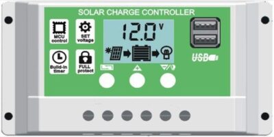
KEY FEATURES
- Controller: PWM; 30A nominal rated charge output.
- System: 12V / 24V automatic; Lead-acid, lithium, and LiFePO4 selections.
- PV boundary: Not published maximum Voc; Not published maximum PV power.
- Controls: LCD, buttons, and dual USB; No app or communications port.
- Best fit: Very small budget systems needing local load control and selectable battery modes.
PROS
- Low-cost PWM control can serve simple 12V or 24V projects.
- Local display and programmable load modes support basic automation.
- Battery-first setup is straightforward when the delivered manual is clear.
CONS
- Menu labels and revisions can make configuration ambiguous.
- Major PV, terminal, and load-current limits are unpublished.
- Generic battery presets require battery-specific verification.
Editor's Choice
Editorial assessment based on exact-model documentation and qualitative exact-ASIN owner evidence; no first-party bench test or population-rate claim
Price and availability subject to change
Will the EpRec 30A PWM Fit Your Solar Array?
Estimate required charging current and check it against the documented limits for EpRec 30A PWM.
Solar Charge Controller Size Calculator
What size charge controller do I need?
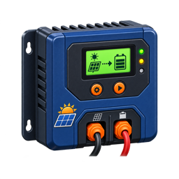
The EpRec 30A PWM is a generic-looking budget controller with a surprisingly broad menu: automatic 12V/24V operation, lead-acid, lithium-ion, and LiFePO4 selections, four-stage PWM charging, an LCD, programmable load control, and dual USB.
Its owner evidence shows why menu labels are not enough. One detailed reviewer explained how newer and older revisions use the same B1/B2/B3 labels for different profiles. Another could not combine LiFePO4 selection with a 24V system and returned the controller. A third said three units displayed 0.4V high and undercharged batteries. With no verified PV Voc, Isc, power, terminal, environmental, or warranty limits, exact revision identification is essential.
| Best For | Useful Capability | Main Risk | Evidence Confidence |
|---|---|---|---|
| Tiny, supervised systems where local load control matters | Multiple chemistry menus at very low cost | Revision/profile ambiguity and missing array limits | Low-to-medium for small 12V use; low for 24V lithium or 30A operation |
Connection Order Is the First Configuration Tool
The broader exact-ASIN owner evidence makes the EpRec’s central issue clear: inexpensive PWM controllers can look interchangeable while their menus, default profiles, labels, and internal revisions differ. Owners describe successful low-cost charging and useful load scheduling, alongside confusion about setup, battery types, display readings, output, failures, and support. These accounts define a verification sequence rather than a product-wide success or failure rate.
Battery-first connection matters because the controller uses the battery to establish its operating reference and automatically select 12V or 24V. Connecting solar first can leave a generic controller in an undefined or misleading state. After connecting the battery, compare the displayed voltage with a meter at the controller and at the battery posts. Voltage drop between those locations can cause the controller to end or resume charging at the wrong battery state.
| Screen item | What to verify | Why it matters |
|---|---|---|
| Battery symbol or code | Map it to the delivered manual, not a similar online photo | Revisions may use different labels |
| Charge voltage | Compare with battery-maker limits | Generic presets may not fit the exact bank |
| Load mode | Test manual, dusk-to-dawn, timer, and disconnect states | A wrong icon can leave a load off or drain the battery |
| System voltage | Confirm 12V or 24V after a full restart | Automatic selection depends on the initial battery state |
The reviewed specification set does not publish PV Voc, PV current, PV power, terminal size, or continuous load-output current. Do not fill those blanks with values from a visually similar controller. Keep the array and load conservative or obtain exact-revision documentation. An inverter belongs on a protected battery circuit, not on the controller’s programmable load terminals.
The EpRec fits supervised small systems where the buyer can confirm every menu item and electrical value. If the installation will be remote, expensive, or difficult to access, revision-stable documentation and support should outweigh the initial price difference.
B1, B2, and B3 Do Not Mean the Same Thing Across Revisions
That method may help identify a received unit, but it is not an official revision matrix in the supplied evidence. Battery settings should be confirmed from the model label, firmware, and current documentation. A mislabeled or mismatched manual is itself a reason to pause.
| Menu Label | Owner-Described Newer Meaning | Reported Revision Risk | Required Confirmation |
|---|---|---|---|
| B1 | Lead-acid | Exact subtype/voltage behavior unclear | Current manual and battery specification |
| B2 | 3S lithium-ion, 12.6V maximum | Older units may show lead-acid-like voltage | Displayed parameters and seller revision |
| B3 | 4S LiFePO4, 14.6V maximum | Not established on every model | Exact firmware/profile table |
| 24V operation | Automatic at battery connection | One owner could not retain 24V with LiFePO4 | Verify before connecting PV |
Profile rule — Never connect an expensive battery merely to discover what B2 or B3 means. Establish the exact revision and every charging value first.
Battery-First Connection Is Repeatedly Emphasized
The detailed owner said battery connection must occur before the solar panel so the controller detects 12V or 24V from a stable source. According to that account, connecting a typical “12V” panel first could make the controller interpret roughly 20V-plus PV as a low 24V battery and apply the wrong configuration.
The product’s automatic detection makes connection sequence logically important, but the exact current manual—not an Amazon comment—must govern. Begin with both sources isolated, verify polarity and battery voltage, connect in the specified sequence, confirm the detected system and profile, then energize PV.
| Commissioning Stage | What to Observe | Stop Condition |
|---|---|---|
| Battery identified | Stable voltage and correct 12V/24V selection | Wrong system voltage or unstable display |
| Chemistry selected | Profile values match battery manual | B-label meaning cannot be proven |
| PV introduced | Voltage inside documented controller range | PV limit absent or connection sequence uncertain |
| Load enabled | Correct low-voltage and timer behavior | Gate/fridge/inverter has unknown surge |
| Full-sun check | Stable voltage/current and cool connections | Heat, resets, or meter mismatch |
One gate-operator owner eventually used a 30W panel and 20Ah LiFePO4 battery after struggling with the instructions. The load output did not operate the gate correctly, so the owner connected the gate to the battery. That is a plausible small charging use case and a warning that controller load behavior may not suit inductive or electronic equipment.
The 24V LiFePO4 Report Exposes a Configuration Limit
Before using any 24V lithium bank, reproduce configuration with no PV and verify the actual charge ceiling against the battery maker. “12V/24V automatic” may describe lead-acid behavior rather than every lithium profile on every revision.
The controller documents no external temperature sensor or low-temperature cutoff. A LiFePO4 system that can freeze needs a BMS or external control proven to stop charge. A voltage preset does not provide temperature protection.
24V lithium verdict — Until exact revision documentation confirms simultaneous 24V and LiFePO4 configuration, this controller should not be recommended for that application.
Three Units Allegedly Read 0.4V High
A high displayed voltage could make the controller believe the battery reached its charge threshold before the terminals actually did. Conversely, differences between the controller and battery can come from cable resistance under current. Measure at both points with an appropriate meter and record load/charge state.
| Possible Source of 0.4V Difference | Diagnostic | Correct Response |
|---|---|---|
| Controller calibration | Compare several known voltages with suitable meter | Return/replace if outside acceptable specification |
| Cable voltage drop | Measure simultaneously at controller and battery under current | Shorten/increase conductor within terminal limits |
| Loose connection | Inspect, torque, and measure across termination | Repair before further charging |
| Different measurement timing | Log readings together | Avoid comparing transient values |
| Wrong profile | Inspect actual charge target | Select documented battery settings |
No terminal wire size or torque is published in the reviewed record, so even cable-drop remediation is constrained. Never force larger wire by removing strands.
PWM Topology Limits the Panel Choices
The nominal 30A output does not establish maximum PV voltage, Isc, or watts. All three are missing. PWM works best with a panel operating voltage reasonably matched to the battery; it does not convert excess PV voltage into proportionally more charge current like MPPT.
The 30W gate-panel example is a conservative scale. A review about powering a small fridge gives no panel, battery, duty-cycle, or measurement details and cannot validate a larger array. Until a reliable manual supplies the envelope, a near-30A installation would be guesswork.
| Design Question | EpRec Evidence | Decision |
|---|---|---|
| Cold-corrected PV Voc | Not published | Do not create series strings from the 30A label |
| Maximum array Isc | Not published | Keep current modest or select documented hardware |
| PV power at bank voltage | Not published | No responsible maximum-watt recommendation |
| PWM matching | Topology known | Use voltage-matched panels, not high-Vmp modules |
| Terminal capacity | Not published | Resolve before conductor purchase |
Load Output and USB Need Narrow Expectations
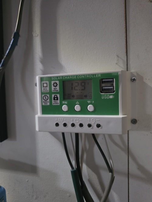
The programmable load circuit offers manual or timed control, but its continuous rating is not published in the normalized evidence. The gate operator failed to work correctly from the load output. Motors, compressors, and refrigerators can have startup currents several times their running load; an inverter introduces another surge layer.
Connect high-current equipment through correctly sized battery-side protection. Use controller load logic only if the exact rating and external switching arrangement are documented. Dual USB can power small electronics, but the output rating and thermal behavior should be confirmed.
Owner Sentiment Is Not the Same as Evidence Quality
| Review Type | Example | Evidentiary Weight |
|---|---|---|
| Specific configuration | 30W panel, 20Ah LiFePO4, gate operator | High for use-case detail |
| Repeated instrument complaint | Three units reportedly 0.4V high | Material caution, incomplete method |
| Exact incompatibility | 24V LiFePO4 selection failed | Material model/revision caution |
| Generic “robust/efficient” praise | No measurements or setup | Low |
| One-line “works with lithium” | No voltage or duration | Very low |
Protected Mounting Is Mandatory
No IP rating, dimensions, operating range, or warranty were published in the reviewed evidence. The controller belongs inside a dry, ventilated, noncombustible space. Leave the display and terminals accessible because revision verification and meter checks are part of ownership.
Provide battery-adjacent overcurrent protection, a PV disconnect, correctly sized conductors, and polarity checks according to the exact equipment manuals and applicable rules. Do not use a controller protection claim as a substitute for fusing.
EpRec-Specific Checklist
- Match the received model and manual before identifying B1/B2/B3.
- Verify displayed charge values without the panel connected.
- Confirm whether the intended 12V/24V and chemistry combination is supported.
- Use the exact battery-first or manufacturer-specified connection sequence.
- Obtain PV Voc, Isc, watts, terminal size, and torque before scaling the array.
- Compare controller and battery voltage with an appropriate meter.
- Keep LiFePO4 cold protection in the battery/BMS unless documented otherwise.
- Test the load output only with a known modest DC load.
- Keep motors, refrigerators, and inverters on protected battery circuits.
- Mount dry, ventilated, visible, and easy to isolate.
Alternatives with Clearer Boundaries
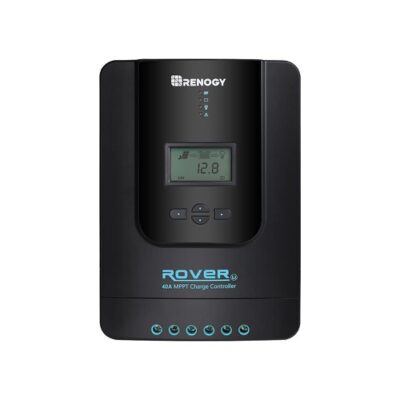
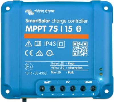
The Renogy Wanderer 10A publishes a 50V ceiling, 130W/260W power table, and terminal limit. It has less headline current but a more designable envelope. The Victron 75/15 adds MPPT, explicit PV Isc, app history, and a five-year warranty. For 24V LiFePO4, either is a better starting point only after its own profile and temperature checks.
If the reason for considering EpRec is dual USB or a timer, compare a dedicated fused USB converter or load controller. Separating accessory power from battery charging can produce clearer ratings and simpler replacement when one function fails.
Pros & Cons Analysis
Based on documented specifications and owner feedback
Pros
- Very — Very low price.
- LCD — LCD and dual USB.
- Four-stage — Four-stage PWM charging.
- Lithium — Lithium and lead-acid modes.
Cons
- Check: No verified PV Voc or Isc limit.
- Check: No weather rating.
- Check: No communications.
- Check: Sparse long-term documentation.
Bottom Line: Too Much Revision Uncertainty for Broad Use
Verdict: The EpRec can serve a very small, carefully verified system, and its menus/load controls are unusually flexible for the price. The evidence does not justify a 30A recommendation.
Best reason to consider it: You already possess a confirmed newer revision for a modest 12V battery and can independently verify every setting.
Reason to skip: Ambiguous manuals, a reported 24V LiFePO4 conflict, three alleged 0.4V errors, and missing electrical limits make documented alternatives more responsible.
Frequently Asked Questions
Is the EpRec 30A PWM MPPT or PWM?
The exact model is documented as PWM. That topology does not replace checks of PV voltage, input current, output current, and battery compatibility.
What battery voltage does the EpRec 30A PWM support?
12V / 24V automatic. Confirm detection and selection behavior in the current exact-model manual.
What is the maximum PV voltage?
Not published. Use cold-corrected array Voc rather than the panel's warm-day value.
How much solar can it handle?
Not published. The PV voltage, PV current, and battery-side charge-current limits must all be satisfied at the same time.
Does the EpRec 30A PWM work with lithium batteries?
Lead-acid, lithium, and LiFePO4 selections. Match every charging value and low-temperature strategy to the battery documentation.
Does it include app monitoring?
No app or communications port. Verify whether any required accessory is included in the exact bundle.
Can I connect an inverter to its load terminals?
Normally no. High-current and surge loads should use a correctly fused battery-side connection unless the controller manual explicitly permits the planned load.
Who should buy the EpRec 30A PWM?
Very small budget systems needing local load control and selectable battery modes.
Technical Specifications
| Brand | EpRec |
|---|---|
| Exact model / revision / ASIN | 30A PWM (ASIN B07VDWTWTW) |
| Controller type | PWM |
| Rated battery-side charge current | 30A nominal |
| Supported battery-system voltage | 12V / 24V automatic |
| Battery chemistry and profile support | Lead-acid, lithium, and LiFePO4 selections |
| Maximum PV open-circuit voltage (Voc) | Not published |
| Maximum PV short-circuit/input current (Isc) | Not published |
| Maximum PV power by battery voltage | Not published |
| Minimum PV/start voltage requirement | Not published for the reviewed revision |
| Load output and low-voltage disconnect | Programmable load output; exact continuous current not published |
| Grounding topology | Not published for the reviewed revision |
| Charging stages and custom voltage control | Four-stage PWM with adjustable parameters |
| Temperature sensing and lithium low-temperature behavior | No external sensor or low-temperature cutoff documented |
| Display and local controls | LCD, buttons, and dual USB |
| App, communications, and data history | No app or communications port |
| Maximum terminal conductor size | Not published |
| Controller self-consumption | Not published for the reviewed revision |
| Published tracking/conversion efficiency | Not published |
| Cooling method and thermal derating | Natural convection; the listing requires ventilated mounting but publishes no derating curve |
| Electrical protections | Reverse-current, overtemperature, undervoltage-disconnect, short-circuit, open-circuit, overload, and overcharge protection |
| Enclosure, ingress rating, and operating temperature | Protected dry mounting; operating range not published |
| Certifications | Not published for the reviewed revision |
| Dimensions, weight, and included accessories | Not published |
| Warranty | Not published |