
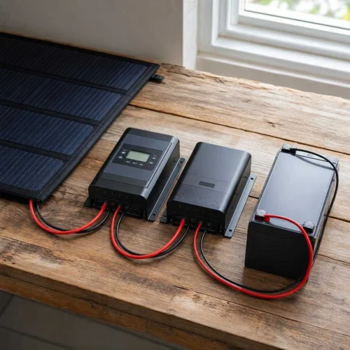
MPPT vs PWM charge controller selection depends on the array operating voltage, battery requirements and intended use. MPPT can convert higher-voltage panel power into lower-voltage charging current; PWM is appropriate only when its documented array and battery requirements fit. Neither technology label guarantees a particular daily energy gain, lithium protection or permission to exceed an input limit.
The useful comparison is what happens to the panel operating point in your system. MPPT can convert higher-voltage panel power into lower-voltage charging current; PWM does not provide that same conversion. The size of the advantage depends on the module curve, battery voltage, temperature and operating conditions. A claimed fixed percentage is not a substitute for those inputs.
MPPT vs PWM Charge Controller: Compare the Operating Point
Assign Regulation Before Considering Extra Harvest
A battery requires controlled charging appropriate to its chemistry and condition. The panel supplies variable power, while the controller applies the permitted charging behavior within its own operating envelope. A controller should not be treated as a device that makes any array or battery combination safe simply because it sits between them.
Separate two decisions. First establish whether the complete system is electrically compatible. Only then compare whether one conversion approach provides a useful performance or service advantage. A product that promises better tracking but omits essential input limits leaves the first decision unresolved. Documentation is part of the comparison, not an administrative detail after purchase.
Record the panel model, string layout, intended battery bank and available installation space. An existing voltage-matched maintenance system presents a different question from a new roof array with long cable runs. Both may have a sensible controller choice without declaring one technology universally unsuitable.
Understand Switching Before Comparing Efficiency
Follow the Panel While a PWM Switch Conducts
A PWM controller switches charging on and off as part of its regulation. During conduction the panel operates near battery voltage, allowing for circuit drops. The available current follows the panel’s current-voltage curve at that point, rather than necessarily matching the current printed beside maximum-power voltage on the label.
For a compatible panel and bank, this can provide useful charging with a relatively simple architecture. PWM is not confined to one universal panel-watt threshold. The exact unit still determines supported bank voltages, PV voltage ceiling, input current, charging profile and thermal limits. Do not use the amp rating without establishing what circuit and conditions it describes.
Avoid describing the unused voltage as heat that must all be dissipated inside the controller. Moving the module away from its maximum-power operating point changes how much power is extracted. That distinction helps explain performance without inventing an efficiency percentage for every PWM design.
| Device | Normal job | Does not replace |
|---|---|---|
| Controller | Regulate compatible PV charging | Circuit protection |
| Battery protection | Respond to cell limits | Normal charge regulation |
| Inverter | Convert DC into AC | Solar input control |
Follow Power Through MPPT Conversion
An MPPT controller adjusts the array operating point while converting power to the battery-side voltage. When PV operating voltage is higher than battery charging voltage, battery-side current can exceed PV operating current while output power remains lower than input after conversion losses. The apparent gain in amps is not a gain in energy.
Tracking and conversion are related but separate. Tracking concerns finding a useful point on the array’s power curve. Conversion concerns transferring the extracted power through the electronics. Product claims may describe peak performance under selected conditions; they do not determine daily yield across shade, heat, battery state and changing irradiance.
Some shade patterns create more than one local peak. How well a particular controller handles those conditions depends on its algorithm and the array, not merely the presence of MPPT on its label. Keep manufacturer claims tied to the exact product and stated conditions.
Separate Conversion Efficiency From Extra Harvest
Compare Percentages Only When Their Denominators Match
Conversion efficiency compares output power with input power under specified conditions. Additional harvest compares energy from alternative systems over a defined period. They are not the same percentage. A highly efficient converter cannot deliver energy that the panel did not supply or the battery could not accept.
There is no guaranteed 15–30% improvement that applies to every MPPT replacement. Cold modules may offer more voltage headroom, but battery acceptance, irradiance, startup requirements and operating losses still matter. Very low light can leave so little available power that a broad percentage claim says little about useful watt-hours.
For a defensible comparison, use equivalent arrays, weather and battery opportunities, or a transparent model that identifies their differences. Record whether the battery was already full and whether loads consumed energy during the observation. A controller’s peak-current screenshot alone cannot establish an annual energy advantage.
| Quantity | PWM simplification | MPPT simplification |
|---|---|---|
| Panel data | 20V Vmp; 5A Imp | 20V Vmp; 5A Imp |
| Assumptions | 14V battery; current stays at 5A | 95% conversion efficiency |
| Illustrated power | 70W | 95W |
| Conclusion | Not measured daily energy | Not a guaranteed yield advantage |
Compare the Tasks Each Technology Must Perform
A controller type should be judged against the actual job. A modest maintenance load can favor low system complexity when the PWM unit explicitly supports the panel and battery. Higher-voltage strings or long cable runs can make an MPPT architecture useful, provided the cold-voltage and current checks pass.
Lithium compatibility is not a synonym for MPPT. It depends on charge targets, stage behavior, current limits, temperature protection and coordination with the battery. A documented PWM product may support a specific lithium battery, while an MPPT product with unsuitable settings or missing cold protection may not.
Compare the full installed system rather than an unsourced controller-price range. Accessories, sensing, enclosure, cabling and maintenance access can change the practical difference. A radio or app feature should earn its place by helping the operator configure or diagnose the equipment, not by standing in for electrical capability.
Compare Two Simplified Operating Points
For a hypothetical 20V, 5A operating point and a 14V battery charging point, the panel represents 100W at maximum power. A simplified PWM estimate is 70W if current remains 5A. An MPPT conversion at an assumed 95% yields 95W before other limits. The difference belongs to this illustration, not every climate or panel. Hot modules, a nearly full battery or a limited load can narrow the usable advantage. Check electrical compatibility before interpreting any efficiency result.
Open calculation toolOptional · use your own values or a labelled example
Use hypothetical maximum-power voltage/current and battery charging voltage to compare two simplified power paths. The PWM estimate assumes panel current remains near the entered Imp when pulled toward battery voltage; the actual current-voltage curve may differ. The MPPT estimate uses an explicitly assumed conversion efficiency. Neither output predicts annual yield or approves an array.
The interactive worksheet requires JavaScript. The worked explanation below remains available; do not treat missing output as a passed check.
Educational screening only. This worksheet cannot inspect equipment, verify an installation or approve energizing.
Match Controller Type to the Existing Array and Battery
Keep a Working PWM System When the Evidence Supports It
A replacement is not automatically valuable merely because another technology is available. If the existing PWM system meets the seasonal energy need, has compatible charging behavior and passes the equipment limits, identify the remaining problem before purchasing a replacement. That problem might be none, or it might be a poorly located panel rather than conversion.
Look at usable energy across the period that matters. A maintenance application may have little use for extra midday production once the battery is at target. A regularly depleted bank may benefit differently. Keep observations of battery state and loads beside controller history so the decision reflects what could actually be stored or used.
Do not interpret a functioning setup as proof of correct wiring or winter voltage. Retaining equipment still requires checking its documentation and condition. Changing panels, battery chemistry or bank voltage makes it a new compatibility assessment even when the old controller remains mounted.
Choose MPPT for a Specific Array or Operating Requirement
MPPT can be attractive when the array’s useful voltage sits well above the battery charging voltage, or when an approved series layout reduces PV-cable current for a longer run. Higher voltage also changes shock and equipment-rating requirements; it is not simply a free improvement in cable performance.
Check the useful lower voltage boundary as well as maximum Voc. A hot array may have lower operating voltage, and a controller can require additional voltage to start before it can continue tracking. Selecting a higher-voltage bank without checking this window can prevent useful charging even though the cold ceiling passes.
Prefer an exact model that documents the required functions and limits. A larger charge-current number does not establish a higher input-voltage ceiling, and a different member of the same family can require a different layout or accessory. Match the final SKU to the design record.
Check a Small-Array Example Without Universal Gain Claims
Use Independent Sizing Gates on Either Technology
Estimate battery-side demand from array watts divided by a realistic charging voltage, with an explicit efficiency assumption when useful. Then check the manufacturer’s output and thermal rules. This is one preliminary estimate, not a substitute for the controller’s input-voltage and input-current specifications.
Cold-corrected Voc must satisfy the exact input ceiling with any required margin. Design PV current must satisfy the applicable input rule and its required factors. Proposed watts must fit the documented row or explicit overpaneling policy for the actual bank voltage. Battery limits include all simultaneously available charging sources.
Do not add a blanket percentage to output amps and claim that it solves cold-voltage risk. These quantities belong to different checks. A conductor, protection or terminal problem also cannot be repaired by choosing a larger number on the controller’s charge-current label.
| Boundary | Evidence needed | Do not substitute |
|---|---|---|
| Maximum PV voltage | Cold-corrected array Voc | Nominal panel voltage |
| PV input current | Array Isc and required factors | Battery output amps |
| Charging output | Bank-specific power and current allowance | Input voltage ceiling |
| Battery acceptance | Combined charger limits | BMS emergency disconnect |
Read a 200W Example Without Rounding Down a Requirement
For a hypothetical 200W array charging at 14.4V, dividing watts by charging voltage gives approximately 13.9A before conversion losses or other limits. At an assumed 95% conversion efficiency, the illustrative current becomes about 13.2A. Neither figure proves that a particular 15A or 20A controller is suitable.
You still need module Voc, the correct temperature coefficient, string layout, design temperature, input-current limits, permitted array watts, battery current and mounting conditions. On a higher-voltage bank the arithmetic current falls, but the panel may no longer provide enough operating voltage. Do not call a smaller controller sufficient until those other requirements are known.
If a documented requirement calculates above a device rating, rounding it down does not create compliance. Choose a supported design or revisit the assumptions through the proper manual-based method. The result should show which boundary drove the selection rather than concealing it inside a generic headroom rule.
Keep Shared-Battery Controllers and Station Inputs Distinct
Coordinate Controllers That Share a Battery
Separate controllers may charge a shared bank when the equipment and battery instructions permit the architecture. Each needs its intended PV source, appropriate protection and compatible charge behavior. Do not connect one array to multiple unrelated tracker inputs as an improvised method of sharing power.
Matching a chemistry label is not enough. Check the actual voltage targets, temperature policy, simultaneous current and response to BMS inhibition or a disconnected battery. One charger can affect the voltage observed by another, so charge-stage behavior should be understood in the combined system.
If only one controller’s array changes, revisit the battery-side total as well. Two individually acceptable output limits can exceed what the bank permits together. Save the final settings and source layout so later service does not treat the chargers as isolated installations.
Respect an Integrated Station’s Solar Input
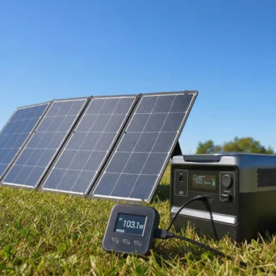
Many portable power stations already contain a solar charging controller. Their input port has a defined voltage range, current allowance, power limit, connector and polarity. Follow that complete specification rather than buying another controller to put in front of it automatically.
An external battery charger output is not automatically a compatible PV source for a station. Additional conversion can introduce startup or control interactions, and physical connector fit does not establish approval. Use external equipment only when the station and connected device explicitly support that path.
For a station owner, the more useful shopping question is often which panel or string matches the integrated input. Keep that question separate from selecting a standalone controller for a separate battery bank.
Choose the Technology That Fits the Documented System
Finish the Choice With a Written Reason
Choose PWM when its complete documented envelope suits the array, battery and energy task. Choose MPPT when its conversion, array flexibility or required features solve a specific need within the permitted limits. Do not force either choice from a universal gain percentage, a small-panel cutoff or the presence of lithium in the system.
Write down the decisive requirement and the remaining installation checks. Keep cold voltage, current, battery profile, temperature controls and protection in the record, even if they did not distinguish the two finalists. A controller can be a good purchase only within a system it actually supports.
- Record exact panel and battery models.
- Check cold Voc and hot operating voltage.
- Check input current, permitted array power and output current separately.
- Verify chemistry, temperature control and all charging sources.
- Document installation and protection requirements.


Leave a Reply