
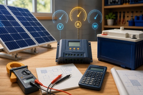
To learn how to size a solar charge controller, check cold-corrected array Voc, total PV Isc, estimated battery-side charge current, the manufacturer’s PV-watt allowance at your bank voltage, and the battery or BMS current limit. Each is a separate pass/fail gate. A controller that passes watts but fails winter Voc is unsafe, while a larger amp label cannot repair that mismatch.
Sizing starts with the proposed array and battery, not the controller’s headline amps. The cold-voltage worksheet below handles one gate that is easy to miss: module Voc at the site design-low temperature. It does not silently substitute a generic cold-weather percentage. Keep the panel’s coefficient and its units beside the calculation so another person can reproduce it.
How to Size a Solar Charge Controller From a Complete Input Record
Why a 40A Label Cannot Size the PV Input
Imagine two 40A controllers: one accepts 100V PV Voc and another accepts 150V. Their charge output can be identical while the safe series-string layouts differ. Input-current allowances, bank-specific watts, terminal sizes, and temperature derating can also diverge.
Sizing therefore works like a checklist of independent constraints. The first failed constraint eliminates the candidate or forces an array redesign. Surplus capacity in a different row does not create a trade.
| Source Document | Fields to Collect | Do Not Substitute |
|---|---|---|
| Panel data sheet | Pmax, Voc, Vmp, Isc, Imp, Voc temperature coefficient, maximum series fuse | Nominal “12V panel” label |
| Controller manual | Max PV Voc, MPPT window, max PV Isc/input current, charge amps, PV watts by bank voltage | Product-title amp number |
| Battery manual | Charge voltage, maximum charge current, temperature limits, BMS behavior | Generic chemistry preset |
| Site/climate basis | Minimum design temperature, conductor environment, expected heat | Today’s weather |
Calculate Cold String Voltage Before Selecting the Current Class
Step 1: Fix the Proposed Electrical Architecture
Start with actual module count and a proposed series/parallel arrangement. “Four panels” is not enough: four in series, four in parallel, and 2S2P create different voltage and current. Also define battery nominal voltage, chemistry, capacity, and other chargers.
Record whether expansion is real or speculative. A future second string changes Isc; more modules in series change Voc; a 24V battery conversion changes the controller’s permitted watts. Buying arbitrary headroom without an architecture can still produce the wrong controller.
| Design Input | Example Entry | Why It Is Needed |
|---|---|---|
| Module model/count | Four matched 200W modules | Establishes exact electrical data |
| String plan | 2S2P | Determines voltage and current multiplication |
| Battery | 24V LiFePO4, exact model | Selects watt row and charge limits |
| Minimum temperature | Site design value | Corrects maximum Voc |
| Cable route | Length, temperature, installation method | Supports ampacity and voltage-drop design |
| Expansion | One additional matched string, documented | Tests future Isc and watts honestly |
Calculate a Cold-Voltage Screening Example
For hypothetical modules with 40V Voc and a coefficient of −0.30%/°C, two modules in series at −10°C calculate to 88.4V. That leaves 11.6V below a 100V ceiling before any required additional margin. Three in series produce 132.6V and fail the same ceiling. Neither result checks parallel-string Isc, hot Vmp or battery acceptance. Keep these outputs on the sizing record as one gate rather than turning “below 100V” into an installation approval.
Open calculation toolOptional · use your own values or a labelled example
Use a negative Voc temperature coefficient expressed in percent per degree Celsius, not volts per degree or an unsigned magnitude. Enter the minimum design cell temperature selected using the applicable design method. The tool uses a linear coefficient referenced to 25°C; it is unsuitable when the module documentation requires a different model. Add any manufacturer-required margin separately.
The interactive worksheet requires JavaScript. The worked explanation below remains available; do not treat missing output as a passed check.
Educational screening only. This worksheet cannot inspect equipment, verify an installation or approve energizing.
Check Parallel-String Current Against the Correct Input Limit
Step 2: Calculate Cold-Corrected Array Voc
Open-circuit voltage rises as solar cells get colder. First add module Voc through one series string:
array Voc at STC = module Voc × modules in series
Then apply the panel manufacturer’s published Voc temperature coefficient using the required design method and site temperature. Coefficients may be shown as percent per degree or volts per degree; preserve units and sign. Do not apply an unexplained blanket percentage as the final method.
| Voltage Check | Input | Hypothetical Result | Status |
|---|---|---|---|
| Panel Voc at STC | 24.0V | — | Source: panel sheet |
| Modules in series | 2 | 48.0V STC string Voc | Preliminary |
| Cold correction | Exact coefficient + design temperature | Must calculate | Incomplete until sourced |
| Controller absolute ceiling | Candidate manual | Compare with corrected Voc | Pass only with required margin |
This hypothetical example deliberately stops before a final pass because no coefficient or site temperature was supplied. That is responsible sizing: missing inputs remain missing.
Also check hot-weather Vmp against the controller’s operating or MPPT window. A string can stay below maximum Voc yet fall too close to battery voltage in high cell temperatures, impairing tracking or charging.
Estimate Charging Demand at the Actual Battery Voltage
Step 3: Add Array Isc Across Parallel Strings
Matched modules in series carry approximately one module’s current. Parallel strings add current:
array Isc at STC = string Isc × number of parallel strings
Apply only the factors required by the exact controller instructions, equipment listing, and applicable electrical rules. The controller may publish maximum PV short-circuit current, maximum operating current, maximum reverse current, or an oversizing policy; these labels are not interchangeable.
| Layout | Voltage Relationship | Current Relationship | Dominant Input Risk |
|---|---|---|---|
| 4S1P | Four module voltages | One module current | Cold Voc |
| 1S4P | One module voltage | Four module currents | PV Isc and conductor/protection capacity |
| 2S2P | Two module voltages | Two module currents | Both checks matter |
| Mixed modules | Depends on mismatch | Depends on branch behavior | Unsupported combination |
If the candidate manual provides no PV Isc or input-current limit, do not use its charge-output rating as a replacement. Request exact-model guidance or choose a controller with a complete data sheet.
Read the Published Watt Row and Battery Restrictions Together
Step 4: Estimate Battery-Side Charge Demand
A useful first-pass estimate is:
approximate output amps = array STC watts ÷ target battery charging voltage
Suppose a hypothetical 800W array charges a 24V bank near 28.4V:
800W ÷ 28.4V ≈ 28.2A
That suggests a controller class above 28.2A before considering real conversion and operating conditions. It does not prove a particular 30A controller passes because cold Voc, PV Isc, manufacturer watts, thermal behavior, and battery current still need confirmation.
| Hypothetical Scenario | Calculation | Preliminary Reading | Remaining Work |
|---|---|---|---|
| 400W into 14.2V | 400 ÷ 14.2 = 28.2A | Near 30A class | Check clipping/margin and 12V watt row |
| 400W into 28.4V | 400 ÷ 28.4 = 14.1A | Near 15A class | Check 24V watt row and PV inputs |
| 800W into 28.4V | 800 ÷ 28.4 = 28.2A | Near 30A class | Check battery and thermal limits |
| 800W into 56.8V | 800 ÷ 56.8 = 14.1A | Near 15A output | Controller must explicitly support 48V |
The table explains why nominal battery voltage changes allowed PV power. Do not infer that a controller supports 48V simply because the arithmetic looks attractive.
Step 5: Use the Correct PV-Watt Row
Manufacturers frequently publish separate array-power allowances for 12V, 24V, 36V, and 48V banks. Select only the row for the configured battery. If the controller supports automatic voltage selection, verify how lithium voltage is selected and how mistaken detection is prevented.
The watt allowance can be lower than a simple current-times-voltage estimate because it reflects product design and policy. It can also include a permitted oversizing region. Follow the exact wording: recommended PV power, nominal maximum, and absolute maximum may mean different things.
| Manual Wording | Safe Interpretation | Required Follow-Up |
|---|---|---|
| Maximum nominal PV power | Normal published array boundary | Confirm whether any oversizing is authorized |
| Recommended PV array | Design target rather than necessarily absolute | Find voltage/current hard limits |
| Maximum input power | Treat as hard unless manual distinguishes clipping | Check bank-voltage context |
| Oversizing up to stated ratio | Conditional permission | Preserve Voc, Isc, thermal, and warranty conditions |
Include Terminals, Heat and the Planned Next Array
Step 6: Check Battery, BMS, and Temperature
The battery may accept less current than the controller can produce. Obtain the continuous charge limit, temperature-dependent limit, and any preferred rate for cycle-life goals. For parallel batteries, use the manufacturer’s rules rather than assuming current shares perfectly.
LiFePO4 requires a verified cold-charge strategy. A controller’s lithium profile can change voltage stages without sensing battery temperature. Determine whether the controller, a remote sensor, the BMS, or a coordinated system interrupts charge, and test how it recovers.
Lead-acid temperature compensation has a different purpose. Sensor placement and voltage reference can matter, especially when the controller and battery are at different temperatures or cable drop is material.
Step 7: Check Terminals, Conductors, Protection, and Heat
How to size a solar charge controller safely includes confirming that the calculated conductors fit its terminals without modification. Ampacity, voltage drop, ambient temperature, bundling, connection method, and protective-device coordination belong in the conductor design. Terminal maximum wire size is not a recommended wire size.
Controllers can reduce output at high ambient or internal temperature. Mounting orientation, clearances, enclosure ventilation, altitude, and simultaneous power all affect usable capacity. A 40A label may not mean 40A continuously in a hot sealed cabinet.
Finish With an Auditable Controller Selection
Step 8: Evaluate Expansion and Overpaneling Separately
Future modules can be added in series or parallel, and those changes stress different limits. Write the future string diagram now, then rerun cold Voc, Isc, output, watts, terminals, and battery acceptance. “I may add panels” is not a calculation.
Some manuals authorize excess PV watts so the controller clips peaks while harvesting more energy in weak conditions. This permission does not authorize excess voltage or input current. If the exact model is silent, ask the manufacturer or stay inside the normal allowance.
Final Pass/Fail Worksheet
- Exact panel Voc coefficient and site minimum temperature are documented.
- Cold-corrected series Voc is below the controller ceiling with required margin.
- Hot Vmp remains inside the useful operating window.
- Total array Isc passes the exact PV input-current rule.
- Estimated battery-side current passes controller output and thermal limits.
- Array watts pass the row for the actual battery voltage.
- Battery/BMS accepts combined charge current and configured voltage stages.
- Low-temperature charging behavior is explicitly assigned and verified.
- Required conductors fit published terminals; protection and disconnects are designed.
- Planned expansion passes the same worksheet, not a verbal headroom assumption.
Any unchecked hard-limit item means the design is incomplete.
Recheck the Exact Variant at Purchase
Manufacturers reuse family names across current ratings, voltage classes, isolated or grounded versions, and regional revisions. Compare the final SKU and manual with the product in the cart. If the marketplace listing combines variants, save the exact model evidence rather than assuming the selected dropdown inherited the displayed specifications.
Repeat the worksheet when any panel, battery, controller firmware policy, or string layout changes. A previously safe calculation does not automatically cover substitute modules with different electrical values.
Bottom Line: Size Every Boundary, Not One Label
To apply how to size a solar charge controller, create a one-page record of cold Voc, hot Vmp, total Isc, estimated output current, bank-specific PV watts, battery limits, terminal requirements, and environment. Cite the panel, controller, battery, and climate source beside each value.
This process selects a preliminary controller class; it does not certify wiring or code compliance. When current factors, fault current, grounding, overcurrent protection, conductor ampacity, or applicable rules are uncertain, have a qualified designer or installer review the complete system before purchase or energizing.


Leave a Reply