SOLPERK 10A Waterproof Review: Verify Polarity Before You Trust It
At a Glance
KEY FEATURES
- Controller: PWM; 10A rated charge output.
- System: 12V / 24V automatic; AGM, gel, flooded, and sealed lead-acid; not lithium.
- PV boundary: Not published maximum Voc; 150W @ 12V; 300W @ 24V maximum PV power.
- Controls: Status LEDs; No app or communications port.
- Best fit: Exposed low-power 12V/24V lead-acid maintenance systems using SAE connections.
PROS
- Sealed packaging and fixed leads suit simple outdoor lead-acid maintenance systems.
- Status LEDs make basic operation visible without menus or an app.
- Low cost fits gates, trailers, and seasonal equipment when loads are modest.
CONS
- Owner reports make overnight reverse-drain testing essential.
- Short leads and every external splice still need weatherproofing and strain relief.
- The simple interface cannot diagnose battery condition or quantify harvested energy.
Editor's Choice
Editorial assessment based on exact-model documentation and qualitative exact-ASIN owner evidence; no first-party bench test or population-rate claim
Will the SOLPERK 10A Waterproof Fit Your Solar Array?
Estimate required charging current and check it against the documented limits for SOLPERK 10A Waterproof.
Solar Charge Controller Size Calculator
What size charge controller do I need?
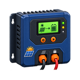
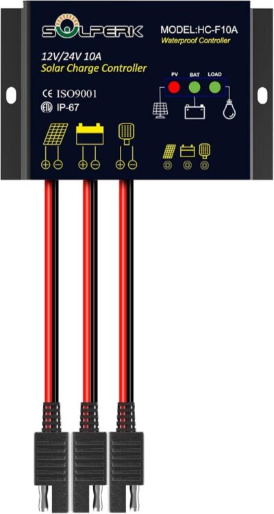
The SOLPERK 10A Waterproof PWM controller is built for a specific job: keeping a modest 12V or 24V lead-acid battery charged in an outdoor installation with convenient SAE connections. Its IP67 enclosure, fixed leads, automatic system-voltage detection, and 150W-at-12V or 300W-at-24V published limits make it appear almost plug-and-play.
The owner evidence says the hardware can work well on UTVs, gates, trailers, and other maintenance systems. It also exposes the checks that a simple product page can hide. One apparent dead-on-arrival report turned out to be reversed polarity; another unit reportedly drained a battery in daylight; a repeat buyer said the first controller began allowing nighttime discharge after about three years; and one unit was genuinely reported dead on arrival.
| Best For | Main Advantage | Main Concern | Evidence Confidence |
|---|---|---|---|
| Exposed, low-power 12V/24V lead-acid maintenance systems using SAE connectors | IP67 body and quick-connect cabling | Polarity, reverse-drain, and longevity must be verified | Medium |
Outdoor Packaging Does Not Eliminate Nighttime Monitoring
The larger exact-ASIN owner record supports the SOLPERK’s narrow role: maintaining 12V lead-acid batteries in gates, trailers, seasonal vehicles, and similar outdoor systems. It also makes the central acceptance test clearer. Several useful accounts praise easy installation and weather-tolerant packaging, while critical accounts describe battery drain, warmth, failed output, or water entering somewhere in the installed circuit. Those reports cannot establish a defect rate, but they justify a measured overnight test before the system is left unattended.
“Waterproof” applies to the controller enclosure under its stated conditions, not automatically to every connector and termination. Mount drip loops, protect the battery-side fuse, keep splices out of standing water, and provide strain relief for the short leads. If an adapter is added, verify polarity with a meter rather than trusting connector gender or wire color alone.
Use the LEDs as a prompt to measure, not as proof of battery health. Log battery voltage at sunset and before sunrise with the load disconnected, then repeat with the intended load. A controller that appears to charge during the day can still be a poor fit if its own consumption, reverse leakage, or the connected equipment exceeds overnight margin. This is a maintenance controller, not a license to pair a small panel with a large continuous load.
The Most Important Test Happens Before Connection
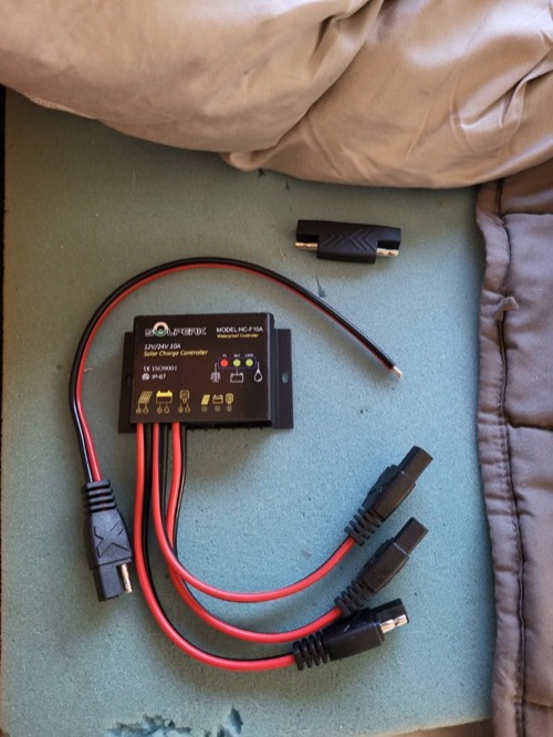
SAE two-pin connectors are mechanically convenient but do not guarantee that every product uses the same polarity orientation. Accessories, extension leads, and polarity-reversing adapters can leave exposed and recessed sides arranged differently. That matters because one supplied buyer initially called this SOLPERK dead on arrival, then updated the review after discovering the polarity was wrong. The controller worked once the connection was corrected.
That correction is better evidence than a generic “easy installation” statement. It shows why color alone, connector fit, or a charging LED is not enough. Identify the positive and negative conductors from the exact instructions and verify them with a suitable meter before joining the panel, controller, and battery.
| Pre-Connection Check | What to Confirm | Failure Prevented |
|---|---|---|
| Controller model | 10A version and correct manual | Applying instructions for a similar SOLPERK controller |
| SAE polarity | Positive and negative at every mating connector | Reverse polarity or a misleading no-power diagnosis |
| Battery voltage | Healthy 12V or 24V lead-acid bank | Connecting to the wrong system or a damaged battery |
| Panel values | Voc, Vmp, Isc, and Imp from label | Exceeding an undocumented controller boundary |
| Cable route | Length, protection, and strain relief | Voltage drop, abrasion, and water entry at a field connection |
Polarity rule — Treat every SAE junction as electrically unverified until measured. Two connectors can fit perfectly and still place positive against negative.
What the Published 10A and Watt Limits Actually Allow
The published specification sets a 10A charge-current ceiling, 150W maximum PV power on a 12V battery system, and 300W on a 24V system. Those values are more useful than an amp label alone, but maximum PV open-circuit voltage and short-circuit current were not available in the reviewed evidence. Without those limits, this article cannot approve arbitrary series or parallel arrays.
One owner used a 100W flexible panel on a Polaris Ranger to charge a large auxiliary battery that powered a 3,000W inverter and heavy tools. That does not mean the controller can run a 3,000W load. The battery and inverter supply the tool power; the controller only replaces energy at the rate available from the 100W panel. The reviewer reported battery voltage around 13.9V under charging and down toward 12.5V with heavy use, but did not publish current or daily energy.
Another buyer said 50W was the maximum. That conflicts with the published 150W/300W specification and appears to be the owner’s conservative interpretation, not the reviewed model’s published rating. Use the exact manual rather than repeating either number without checking the product revision.
| System Question | Supported Answer | Still Unknown |
|---|---|---|
| Rated charge output | 10A | Verified continuous output in hot weather |
| Maximum PV power at 12V | 150W published | Conditions and derating detail |
| Maximum PV power at 24V | 300W published | Conditions and derating detail |
| Maximum PV Voc | Not published in supplied evidence | Safe cold-weather series-string ceiling |
| Maximum PV Isc | Not published in supplied evidence | Safe parallel-array current boundary |
| Battery chemistry | AGM, gel, flooded, and sealed lead-acid | No lithium profile documented |
PWM architecture also affects array choice. A higher-voltage panel does not gain the buck-conversion flexibility of an MPPT controller. Match the module and battery according to the current SOLPERK instructions, and do not treat unused voltage as free charging power.
IP67 Covers the Box, Not the Whole Solar Circuit
The sealed controller body is the strongest reason to choose this model over an exposed indoor controller. Owners specifically valued outdoor use. Yet IP67 applies to the rated enclosure under defined conditions; it does not automatically cover the SAE connector, extensions, fuse holder, splices, panel junction box, or battery terminals.
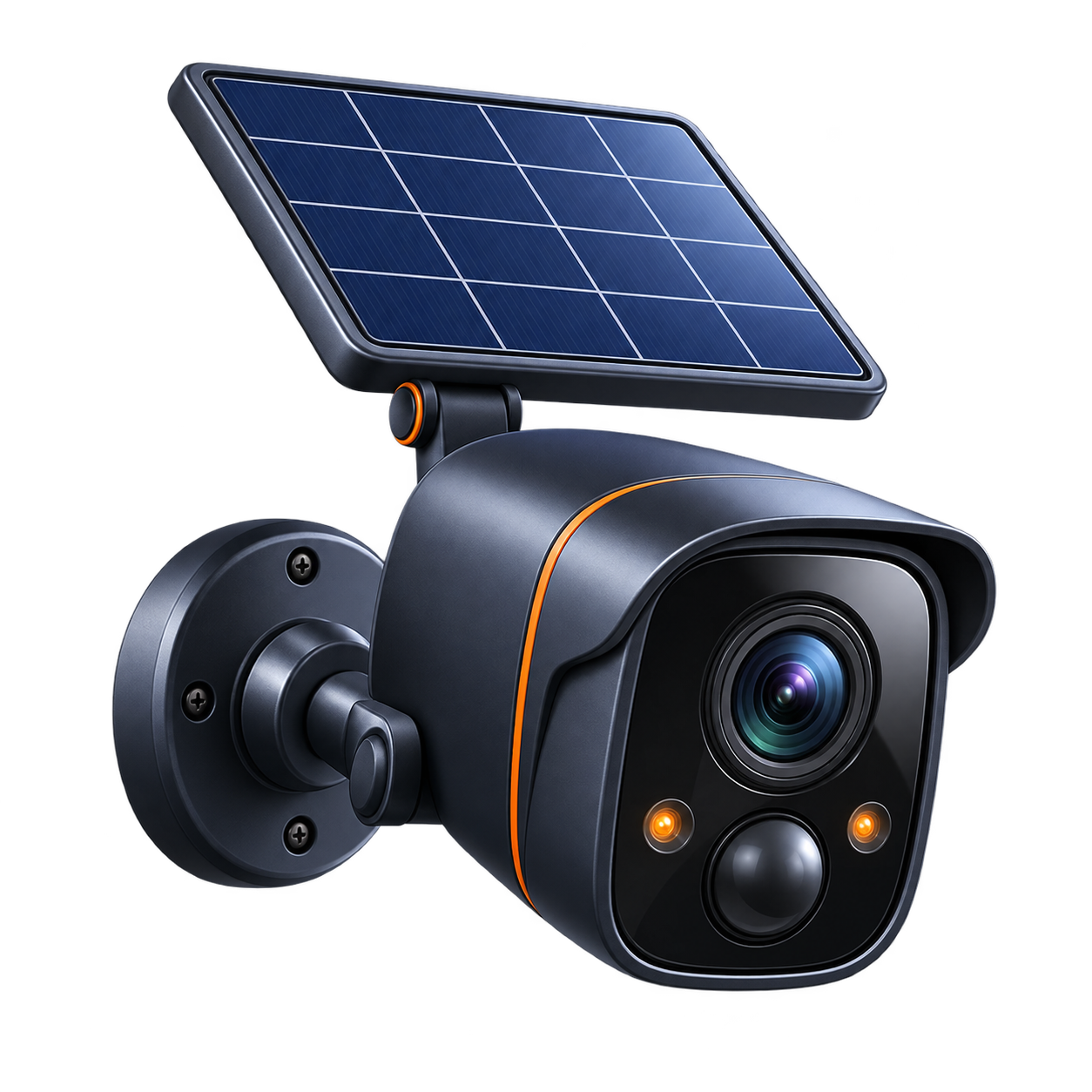
One repeat buyer said they add waterproofing and an additional waterproof 12V connector for a front-gate security-camera installation. That is evidence that experienced users still treat the field connections as separate exposure points. It is not a universal method or proof of the enclosure rating.
| Exposure Point | Protection Supplied | Installation Responsibility |
|---|---|---|
| Controller electronics | IP67 enclosure | Avoid physical damage and unsupported submersion assumptions |
| Fixed cable exit | Factory assembled | Preserve strain relief and prevent abrasion |
| SAE junction | Connector-specific | Confirm environmental rating, polarity, and full engagement |
| Extension cable | Not part of controller rating | Size for current/drop and protect every splice |
| Battery and fuse | Separate components | Provide suitable covers, corrosion control, and overcurrent protection |
The short cable was a practical limitation for a Class A motorhome owner who wanted to mount the controller in the engine compartment. Extending the wire may solve reach but adds voltage drop and another connection. Calculate the run rather than selecting an extension only because its plug matches.
Battery Drain Is the Risk to Monitor
Two supplied reports make reverse current the central reliability question. One buyer connected an AGM battery and 120W panel, started at 12.35V, and returned after weeks of reported direct sunlight to find 12.1V even though indicators looked normal. That result could involve the controller, battery condition, panel output, wiring, shade, or measurement timing; the review did not isolate each cause. It is still a credible warning because the system moved in the wrong direction while appearing active.
A second owner said a first controller lasted about three years before allowing the panel to discharge the battery at night and in low light. They repurchased the unit for a gate opener with a 10W panel. The account combines a meaningful lifespan with a meaningful failure mode. It does not support either “unreliable junk” or “set it and forget it.”
Commissioning rule — A charging light is not proof of positive daily energy balance. Record battery voltage and, ideally, current before installation, in full sun, after sunset, and the next morning.
For an unattended gate, camera, seasonal vehicle, or emergency battery, repeat the nighttime check periodically. A blocking component can fail after years even if initial commissioning was successful. Also investigate battery self-discharge, parasitic loads, shade, dirty modules, damaged wiring, and poor connections instead of assuming the controller is the only possible cause.
Lead-Acid Support Keeps the Use Case Narrow
The reviewed profile supports flooded, sealed/AGM, and gel lead-acid batteries. It does not document a lithium charging algorithm, configurable setpoints, temperature sensing, or low-temperature lithium cutoff. A battery BMS does not transform an unsuitable charging profile into an approved one.
Automatic 12V/24V recognition simplifies replacement installations, but automatic voltage selection cannot determine the battery manufacturer’s preferred absorption, float, equalization, or temperature-compensation behavior. Verify those values against the current instructions, particularly for gel batteries that may be sensitive to overvoltage.
| Battery/Application | Fit | Required Verification |
|---|---|---|
| Small AGM maintainer | Good | Profile voltage and overnight drain |
| Flooded gate battery | Good | Ventilation, water level, charge voltage |
| Gel battery | Conditional | Exact voltage profile must match manufacturer |
| LiFePO4 bank | Not documented | Choose a controller with an explicit lithium profile and cold protection strategy |
| Large inverter bank | Conditional | Controller can maintain slowly; it cannot replace heavy energy use quickly |
There are no documented load terminals. Loads should be connected through a properly designed battery-side distribution and protection system, not improvised onto the controller’s fixed leads. Low-voltage disconnect requirements must be handled separately.
LEDs Make It Easy to Use and Easy to Misread
The controller offers status LEDs, not a numeric display, app, event history, or communications port. That is adequate when the operator only needs a basic solar/battery indication and uses independent instruments during setup. It is weak when the site is remote or the battery is mission-critical.
The Polaris Ranger owner understood this division well: battery and inverter performance were separate from the controller’s limited replenishment role. For a security gate or camera, the useful question is not merely “is the LED on?” but whether the array produces enough daily watt-hours after weather, cable loss, controller loss, and load consumption.
A Responsible SOLPERK 10A Commissioning Sequence
- Photograph the controller label and obtain the matching current manual.
- Verify battery chemistry, nominal voltage, health, and manufacturer charging limits.
- Read the panel label and confirm PV watts plus all voltage/current boundaries.
- Measure polarity at every SAE connector before mating it.
- Install correctly sized battery-side protection and weather-protect field connections.
- Follow the product-specific connection order in the current manual.
- Measure battery voltage and charging current in useful sun.
- Check for voltage drop along any extension and abnormal connector heating.
- Measure for unwanted reverse current after dark.
- Recheck the system after several days and at the start of each season.
How It Differs from the SOLPERK 8A
The 10A model supports automatic 12V/24V operation and publishes useful 150W/300W PV power ceilings. The documented 8A profile is 12V-focused and omits a published PV watt limit. Both use sealed enclosures, fixed leads, LEDs, and a simple PWM approach; both also have owner reports involving possible nighttime leakage.
Choose by exact electrical documentation rather than assuming the 10A is merely the 8A with two extra amps. Their connection instructions, chemistry wording, and internal behavior may differ by revision. An SAE plug and similar casing do not establish interchangeability.
Pros & Cons Analysis
Based on documented specifications and owner feedback
Pros
- IP67 — IP67 weather resistance.
- 10A — 10A PWM rating.
- SAE — SAE quick-connect leads.
- 150W/300W — 150W/300W published power limits.
Cons
- Check: Lead-acid only.
- Check: No display or app.
- Check: Mixed polarity and durability evidence.
- Check: PV Voc and Isc limits not published.
Bottom Line: Convenient Outdoors, but Not Self-Verifying
Verdict: The SOLPERK 10A can be a practical outdoor lead-acid maintainer. The 100W UTV installation, gate use, and several simple positive reports show that the concept works. Published 12V/24V watt limits and an IP67 body are real advantages over an undocumented generic controller.
Best reason to buy: You need an inexpensive sealed PWM controller for a modest, meter-verified lead-acid system using SAE connections.
Reason to pause: Polarity confusion, two drain-related accounts, one true dead-on-arrival report, short leads, and missing PV Voc/Isc boundaries make unattended installation without commissioning a poor idea. Verify polarity and nighttime behavior before trusting the battery to it.
Frequently Asked Questions
Is the SOLPERK 10A Waterproof PWM MPPT or PWM?
The exact model is documented as PWM. That topology does not replace checks of PV voltage, input current, output current, and battery compatibility.
What battery voltage does the SOLPERK 10A Waterproof PWM support?
12V / 24V automatic. Confirm detection and selection behavior in the current exact-model manual.
What is the maximum PV voltage?
Not published. Use cold-corrected array Voc rather than the panel's warm-day value.
How much solar can it handle?
150W @ 12V; 300W @ 24V. The PV voltage, PV current, and battery-side charge-current limits must all be satisfied at the same time.
Does the SOLPERK 10A Waterproof PWM work with lithium batteries?
AGM, gel, flooded, and sealed lead-acid; not lithium. Match every charging value and low-temperature strategy to the battery documentation.
Does it include app monitoring?
No app or communications port. Verify whether any required accessory is included in the exact bundle.
Can I connect an inverter to its load terminals?
Normally no. High-current and surge loads should use a correctly fused battery-side connection unless the controller manual explicitly permits the planned load.
Who should buy the SOLPERK 10A Waterproof PWM?
Exposed low-power 12V/24V lead-acid maintenance systems using SAE connections.
Technical Specifications
| Brand | SOLPERK |
|---|---|
| Exact model / revision / ASIN | 10A Waterproof PWM (ASIN B0946MWYPK) |
| Controller type | PWM |
| Rated battery-side charge current | 10A |
| Supported battery-system voltage | 12V / 24V automatic |
| Battery chemistry and profile support | AGM, gel, flooded, and sealed lead-acid; not lithium |
| Maximum PV open-circuit voltage (Voc) | Not published |
| Maximum PV short-circuit/input current (Isc) | Not published |
| Maximum PV power by battery voltage | 150W @ 12V; 300W @ 24V |
| Minimum PV/start voltage requirement | Not published for the reviewed revision |
| Load output and low-voltage disconnect | No programmable load terminals |
| Grounding topology | Not published for the reviewed revision |
| Charging stages and custom voltage control | Automatic PWM lead-acid charging |
| Temperature sensing and lithium low-temperature behavior | No external sensor or low-temperature protection documented |
| Display and local controls | Status LEDs |
| App, communications, and data history | No app or communications port |
| Maximum terminal conductor size | Fixed SAE leads |
| Controller self-consumption | Described as ultra-low standby consumption; no numeric value published |
| Published tracking/conversion efficiency | Not published |
| Cooling method and thermal derating | Not published for the reviewed revision |
| Electrical protections | Battery undervoltage/overvoltage, output overload, short-circuit, and battery/PV reverse-polarity protection |
| Enclosure, ingress rating, and operating temperature | IP67; operating range not published |
| Certifications | Not published for the reviewed revision |
| Dimensions, weight, and included accessories | Not published |
| Warranty | Not published |