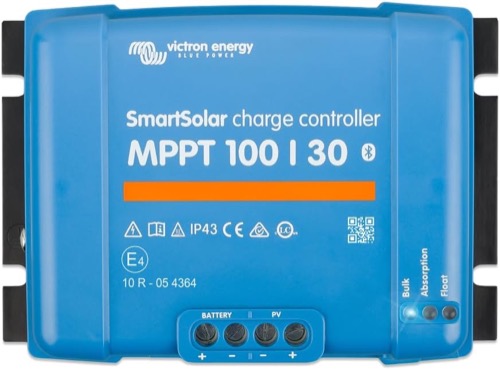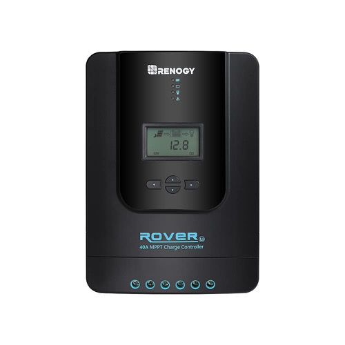
Victron SmartSolar 100/30 vs Renogy Rover 40A compares a 30A controller with integrated Bluetooth against a 40A controller with a numeric local display. Rover earns its extra output when the array and battery can use it. SmartSolar earns its place when 30A is enough and its configuration and monitoring workflow solves the harder ownership problem.
Both featured units are MPPT controllers for 12V/24V battery systems. Neither model in this comparison becomes a 48V charger because a different controller in the same brand family supports that voltage. The model numbers identify specific electrical limits, not a universal brand capability.
We use published model documentation and the existing exact-product review record. The design scenarios are calculations, not results from a Solar Power Picks bench test. They show which unanswered question should be resolved before choosing either controller.
Victron SmartSolar 100/30 vs Renogy Rover 40A: Which Requirement Fails?
List the requirements in order: bank voltage, cold array Voc, array current and power, battery charging acceptance, then controls and total installed cost. A unit eliminated by an electrical limit should not return to the shortlist because its app is attractive or its sale price is lower.
The shared 100V maximum PV ceiling means moving to Rover’s 40A does not buy a higher-voltage series string. Extra output amperage and extra input-voltage headroom are different upgrades. If your cold-corrected array needs more than 100V, both models require a different layout or another controller.
Within a compatible layout, ask whether the extra 10A will reach the battery. A modest array may never supply it, and a battery near full charge may not accept it. The controller should fit the actual charging task rather than simply maximize a number on the specification label.
| Requirement | Preferred candidate | Concession |
|---|---|---|
| 30A sufficient; phone setup used regularly | SmartSolar 100/30 | No numeric display on the enclosure |
| Sustained charge demand between 30A and 40A | Rover 40A | Wiring, battery acceptance and PV rules still govern |
| Phone-free local status reading | Rover 40A | Optional communications must be costed separately |
| Cold string exceeds 100V | Neither | Redesign the array or choose another voltage class |
Model a 12V Upgrade Without Mixing Its Input Limits
Victron publishes nominal PV power of 440W at 12V and 880W at 24V for the 100/30. Rover 40A’s reviewed documentation gives 520W and 1,040W. Use the figures at the same bank voltage, and distinguish nominal conversion capacity from each maker’s permitted oversizing rules.
As an illustrative output calculation, 500W of actual available PV power at 95% conversion and 14.4V charging would support about 33A. That identifies a possible current advantage for Rover while the 100/30 would limit output. It is not approval to attach any 500W arrangement: input current, cold Voc and manufacturer power rules must separately pass.
At 28.8V, the same arithmetic gives about 16.5A. Both output ratings would cover that scenario, so the choice shifts toward controls, documentation and installation. The bank-voltage comparison is especially useful when planning a complete system, although changing an existing bank affects every connected charger and load.
500W × 0.95 ÷ 14.4V ≈ 33.0A; at 28.8V the same assumed input yields ≈16.5A. The 95% factor is an illustrative assumption, not a measured efficiency claim.
Give Panel-Side Current Its Own Approval Line
Victron specifies 35A maximum PV short-circuit current for the SmartSolar 100/30. That is distinct from its 30A battery-charge limit. The reviewed Rover evidence does not establish a comparable exact PV Isc ceiling, so obtain the manufacturer-approved current boundary when finalizing a parallel array.
Series strings add module voltage; parallel strings add current. A 100V label alone therefore says little about whether multiple parallel branches are acceptable. Keep panel Isc, battery-output current and any load-terminal current on separate lines of the design record.
Also check operating voltage across temperature. Cold weather raises module Voc, while heat can reduce the useful operating voltage. Victron’s stated startup requirement is battery voltage plus 5V, reducing to plus 1V once charging continues. Compare actual panel data with the exact Rover requirement instead of assuming shared startup behavior from the shared 100V ceiling.
Clear documentation can favor SmartSolar when an installer needs a complete, auditable string design. That is a documentation advantage, not proof that Rover lacks a capability merely because a value is absent from the reviewed record.
Walk Through a Morning Fault With and Without a Phone
Imagine reaching the controller cabinet after a night of heavy battery use. Rover’s local LCD lets you start with the displayed voltage and status. SmartSolar has status LEDs, while numeric values and detailed settings normally come through VictronConnect or supported external monitoring equipment.
Victron includes Bluetooth and a VE.Direct interface. Rover’s compatible Bluetooth monitoring generally requires the BT-2 accessory on the reviewed model. Add that hardware when comparing an app-equipped system; do not count an optional module as included merely because a bundle photograph shows it.
Local Bluetooth is not internet monitoring from another location. Either ecosystem needs the appropriate additional communications route if remote access is a requirement. Identify the complete route, required devices, power supply and connectivity before assigning either controller an unattended-monitoring advantage.
Test the workflow in the finished cabinet: view values, change an allowed setting, read an error and restore the accepted profile. Save a normal-day record. Owner reports about setup or app friction are useful prompts for these checks, but they do not establish a comparative hardware failure rate.
Inspect Battery Settings, Terminations and the Warm Cabinet
For either unit, compare the selected battery profile with the battery manufacturer’s charging instructions. Verify absorption, float, equalization behavior, accepted charge current and how other chargers interact. A LiFePO4 option is insufficient if the exact required parameters or protections are missing.
Cold-charge inhibition depends on battery-temperature information and the actual control arrangement. An internal sensor used for electronics or ambient compensation does not necessarily measure a distant battery. Establish where the temperature comes from, what stops charging and how the system resumes; check the BMS behavior as part of that plan.
Rover’s higher current can increase the demands on the battery-side conductors and terminations. Victron’s published terminal capacity and Renogy’s published conductor limits must each be checked against the selected cable. More allowed wire size does not itself approve a route; length, insulation, protection and installation conditions also matter.
Neither featured unit should be treated as an exposed waterproof installation. Leave the ventilation and service clearances required by the relevant manual. A controller in a sun-heated compartment may reduce output, and inaccessible terminals make inspection harder. Carry those practical constraints into the comparison before deciding that ten extra amps will always be available.
- Photograph the final battery profile and record the battery model.
- Confirm array voltage and current using the relevant manual limits.
- Check conductor fit, torque, protection and access after mounting.
- Test the intended local and remote diagnosis workflow.
- Observe charging after warm operation and a documented restart.
Choose the interface that the person maintaining the system can actually use. A local screen has value during phone-free visits; saved configuration and history have value when diagnosing an intermittent issue.
Choose Output Headroom or Included Monitoring Deliberately
Choose the SmartSolar 100/30 when the array and bank fit its envelope, 30A is sufficient, and included phone configuration plus the Victron integration path matter. Its honest tradeoff is the absence of a numeric screen on the enclosure and its lower output ceiling compared with the Rover.
Choose Rover 40A when the exact array design is approved, useful charging demand can exceed 30A, or a local LCD is central to maintenance. Include any Bluetooth accessory in the installed price and resolve the PV-input-current rule before finalizing parallel branches.
The Victron SmartSolar 100/30 vs Renogy Rover 40A tie-breaker is the limiting requirement in a real operating day. If it is charge current, Rover can win. If it is a documented configuration and monitoring workflow while 30A already covers the job, SmartSolar can win. Neither conclusion requires claiming a universal winner for every solar system.
Read the 100/30 review and Rover 40A review with Victron’s technical specifications and the Renogy manual for your revision. For a brand-family decision, use the broader ecosystem comparison.