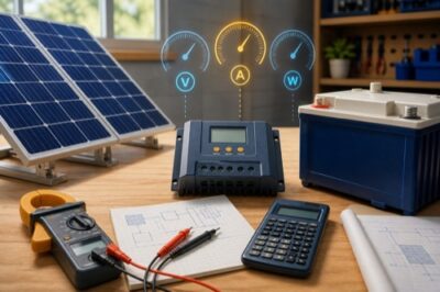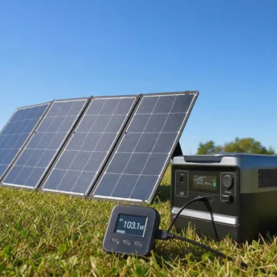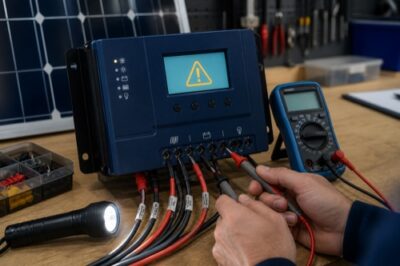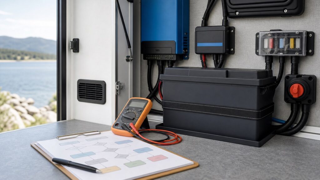
If a LiFePO4 battery is not charging, first stop for heat, swelling, odor, smoke, impact damage, water intrusion, burned or loose connections, unexplained overvoltage, or repeatedly tripping protection. Otherwise, preserve the current readings and determine whether the break is at the energy source, charger/controller, fuse/disconnect/wiring path, temperature interlock, BMS, or battery. Do not begin by bypassing protection or forcing a “wake-up.”
Immediate stop: isolate equipment only by its documented procedure and use qualified help when there is heat, odor, swelling, damaged insulation, corrosion, arcing evidence, incorrect polarity, uncertain fault current, or any condition you cannot measure safely.
Name the Symptom Before Resetting Anything
“Not charging” can describe several different states. Resetting the controller, cycling a disconnect, or changing profiles can erase useful evidence and introduce a second fault.
Zero charge current
The source may be unavailable, the path may be open, charging may be disabled, or the BMS may refuse current.
- Record source and battery voltage
- Record controller stage/fault
- Check temperature and BMS state
Lower-than-expected current
The battery may be near full, solar input may be limited, a stage/current limit may be active, or resistance may be high.
- Compare irradiance and PV input
- Check net loads
- Compare voltage at both ends
Charging starts and stops
Temperature hysteresis, unstable source power, BMS protection, loose/high-resistance connections, or stage logic may be cycling.
- Preserve time-stamped logs
- Correlate voltage/current/temperature
- Stop repeated protection trips
A full or nearly full LiFePO4 battery can accept little current even when everything works. A flat voltage curve also makes state of charge difficult to infer from one resting-voltage reading. Use appropriate BMS/shunt data and the exact manual rather than declaring failure from voltage alone.
First decide whether the number represents gross charger output or net current into the battery. A 20A controller feeding an 18A load leaves only about 2A of net charge, while a shunt wired so one source bypasses it can report an incomplete story. Label the measurement point and current direction in every note.
For solar, panel voltage at the controller with zero battery current does not prove usable power is available. Low irradiance, shade, snow, an open PV path, controller stage logic, or a battery-side disconnect can all produce superficially similar displays.
Locate the Open or Limiting Point
Move through the system by function. Do not disconnect live conductors or probe exposed points unless the exact procedure, test equipment, circuit category, and your training make the action safe.
Solar: record irradiance, PV voltage/current, controller input state, and source-side protection. AC charger: confirm approved input power and charger status. Alternator system: confirm its enable and controller state.
Record profile, stage, current limit, voltage target, temperature input, communications state, and faults. A disabled output or completed stage is different from a failed charger.
Compare safe measurements and state indicators across disconnects, fuses/breakers, busbars, shunt, conductors, and terminals. Do not rely on visual inspection alone.
Check low/high voltage, low/high temperature, overcurrent, short-circuit, communications, and internal fault indicators supported by the exact model.
Use only the documented compatible charger, temperature condition, sequence, and time limit. Otherwise escalate with the recorded evidence.
Source-side evidence
For PV charging, compare array conditions with the exact controller manual: cold-corrected Voc, operating voltage window, PV input current, battery voltage detection, and startup requirements. A controller may need a valid battery connection before it can establish system voltage. Follow its exact sequence rather than copying another brand’s battery-first or PV-first instructions.
For shore or generator charging, distinguish “charger has AC input” from “charger produces compatible DC output.” Input breaker, transfer equipment, remote enable, battery profile, and source quality can all matter. For alternator charging, include ignition/enable logic, DC-DC controller state, and both source and battery protection.
Path evidence
A connection can look tight yet develop resistance, heat, and voltage drop under current. Conversely, an open fuse or disconnect can leave misleading voltage through another sensing path. Use the equipment’s approved inspection and test procedures and the correct terminal torque—not a generic “tighten everything” instruction.
Measure Without Destroying the Story
Capture a time-stamped set before changing settings. The values below are diagnostic categories, not universal acceptable numbers.
| Evidence | What it can separate | What it cannot prove alone |
|---|---|---|
| PV/source voltage and current | Unavailable source versus input reaching charger | Battery permission or charger output |
| Charger stage, target, and fault | Disabled/completed/protected state versus active request | Actual voltage at battery terminals |
| Voltage at charger and battery under load/charge | Possible open path or excessive drop | Internal cell condition without BMS data |
| Clamp current in an identified conductor | Direction and magnitude of current in that path | Net bank current when other paths bypass the measurement |
| Battery/BMS temperature and flags | Documented protection state or recovery condition | Sensor accuracy or all cell temperatures |
| Shunt history | Net charge/discharge trend when every path crosses it | Which parallel battery disconnected |
Use measuring equipment rated and applied for the circuit. If access requires removing covers around unfused battery conductors or live AC, stop and use a qualified technician. A LiFePO4 bank can deliver very high fault current even at low nominal voltage.
Do not change several variables at once. One profile edit plus one reset plus one moved sensor may make charging resume while leaving the actual cause unknown. Preserve the old configuration and change only under exact manufacturer direction.
Repeat a safe measurement only when it answers a named branch. Random retesting can warm a poor connection, drain an already low battery, or cycle protection until the original event disappears from logs. A quiet system with intact evidence is more diagnosable than one repeatedly forced through the same fault.
Read the BMS Branch, Not Just “Protection”
The BMS may block charging while still allowing discharge, block both directions, or appear disconnected to a charger. The permitted recovery depends on the cause and exact product.
Low-temperature charge protection
Confirm cell-representative temperature and the exact recovery threshold. Outdoor air above freezing may not mean cold-soaked cells have recovered. A non-heated battery may need time or an approved external warming strategy.
Low-voltage disconnect
Some exact manuals specify a compatible charger or activation method; other products behave differently. Do not parallel another battery, bypass the BMS, or apply an unregulated source unless the exact manufacturer explicitly directs that procedure.
High-voltage or cell-imbalance event
Preserve pack/cell data, charge target, stage timing, current, and voltage at the battery. Repeatedly raising voltage to “force balance” can worsen the event and must not replace exact balancing guidance.
Overcurrent or short-circuit protection
Remove the cause under the manual’s safe procedure and inspect the complete current path. A reset without resolving load, wiring, conductor, terminal, fuse, or inverter behavior invites another trip.
Communications or internal fault
Save fault codes, firmware, topology, and recent changes. Closed-loop systems may intentionally stop charging when communication is lost; do not defeat that interlock without manufacturer guidance.
The cold-charging guide explains why a permitted temperature range, automatic cutoff, self-heating, and external interlock are separate designs. If your exact model lacks automatic cold protection, a zero-current morning may come from an external controller—or unsafe charging may continue despite the cold.
Recovery Confidence Depends on the Source
Model/revision-specific trigger, compatible charger, temperature, sequence, and limits.
Provide serial, logs, measurements, settings, and photos; save the written direction.
Heater, Bluetooth, BMS, reset, terminal, and voltage behavior may differ.
A successful anecdote cannot establish safe recovery for your battery and system.
A charger with a “0V activation” or “force” function is not automatically suitable. Confirm the battery maker permits that method, the charger recognizes the exact nominal voltage/chemistry, and the battery has not been damaged, overheated, frozen outside limits, physically compromised, or left deeply discharged beyond its instructions.
If charging resumes, keep observing. Stable recovery includes expected voltage/current, no abnormal heat or odor, no repeated fault, and a plausible transition through the documented charge behavior. One momentary amp reading does not clear the original cause.
Send an Evidence Packet, Not “It Is Dead”
When the exact manual does not resolve the state, stop experimentation and send the manufacturer or technician:
- Identity: battery, charger/controller, inverter, monitor, firmware, serial/revision, purchase date, and bank layout.
- Timeline: last normal charge, last load, storage period, temperature history, event time, and recent changes.
- Measurements: source, charger, and battery voltage/current at named points and times, using appropriate instruments.
- States: controller stage, BMS flags, temperatures, disconnect/fuse positions, alarms, and screenshots or exported logs.
- Configuration: saved charge profile, current limits, temperature controls, communications, and other active chargers.
- Physical evidence: clear photos of labels, connections, protection, enclosure, and any damage—without exposing yourself to energized hazards.
- Actions already taken: every reset, disconnection, profile edit, warming step, or recovery attempt in order.
That packet lets support separate a missing source, charger state, high-resistance path, temperature interlock, BMS protection, and internal defect. Until an exact instruction authorizes the next step, leave protection intact; a battery that refuses charge may be doing the safest thing available to it.