
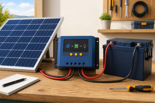
What is a solar charge controller? It is the DC power-conversion and regulation device between a solar array and a rechargeable battery, enforcing input limits and a battery-specific charging profile. It does not replace an inverter, battery-management system, fuses, disconnects, or correct conductors. The exact controller and battery manuals define the safe electrical boundary.
The controller regulates charging; the battery stores energy; the inverter supplies AC. Keeping those jobs separate makes the system easier to understand and its limits easier to check.
What Is a Solar Charge Controller Responsible For?
Why an Unregulated Panel Can Overcharge a Battery
A PV module does not know when a battery is full. Its voltage and available current change with irradiance, cell temperature, and the connected load. Direct connection may push battery voltage beyond the chemistry’s intended profile, and a dark panel can introduce a reverse-current path unless the equipment prevents it.
The controller supervises this transfer. It follows charging stages or a configurable algorithm, limits battery-side current to its capability, and stops or reduces charging at defined conditions. Some models add data logging, load control, temperature sensing, or communication with a larger energy system.
| Component | Primary Job | Important Boundary | What It Does Not Replace |
|---|---|---|---|
| PV array | Converts light to DC electrical power | String Voc, Vmp, Isc, Imp, temperature coefficient | Regulation or battery protection |
| Charge controller | Converts or switches PV power into controlled charging | Max PV Voc/Isc, output amps, bank-specific watts | BMS, fuses, inverter, safe wiring |
| Battery and BMS | Stores energy and protects cells within documented limits | Charge voltage/current, temperature, fault current | Array regulation or branch protection |
| Inverter | Converts DC battery energy to AC | Continuous/surge watts, input current, waveform | Solar charging control |
In plain English, each component has one main job and several interfaces. Good system design checks those interfaces instead of expecting one box to solve every electrical problem.
Place Each Component on the Correct Side of the Battery
Where the Controller Sits in the Power Path
A typical battery-based system follows this functional path: array, PV-side switching and protection, controller, battery-side protection, battery bank, then protected DC loads or an inverter. Exact placement of fuses, breakers, disconnects, grounding, and monitoring depends on equipment listings, manuals, and applicable local requirements.
The controller needs to see a compatible battery and array. Many models use battery voltage to establish operating mode, which is why their manual may require a battery-first energizing sequence. Other equipment can differ, so this common pattern must never be promoted as a universal wiring order.
| Interface | Information to Collect | Why It Matters |
|---|---|---|
| Panel to controller | Cold-corrected string Voc; total Isc; hot Vmp; array watts | Prevents overvoltage and unsupported input current |
| Controller to battery | Bank voltage; profile fields; output amps; temperature logic | Avoids wrong charging behavior or BMS trips |
| Battery to loads | Fault current; conductor ampacity; inverter surge; disconnects | Controller load terminals rarely suit large loads |
| Monitoring network | Port type; accessory; protocol; radio path | Determines what can be configured or logged |
The product can be physically small while handling serious energy. Battery conductors can deliver destructive current into a fault, and a series PV string can remain energized in daylight. Enclosure and service access are therefore part of the controller’s function in the real system.
Separate Regulation From Protection
What Is a Solar Charge Controller Actually Regulating?
The controller responds to battery voltage, programmed charging targets, available PV power, temperature inputs, and internal limits. In a bulk stage it may deliver as much permitted current as conditions allow. Later stages reduce or hold voltage according to the selected battery strategy. The names boost, absorption, float, storage, and equalization vary between manufacturers and chemistries.
| Regulated Quantity | Typical Source of the Rule | Common Mistake |
|---|---|---|
| Maximum charge voltage | Exact battery manual | Copying a value from another LiFePO4 bank |
| Maximum charge current | Battery/BMS plus controller limit | Assuming controller capacity is always acceptable |
| Stage duration/exit | Battery guidance and controller algorithm | Treating every named stage as universal |
| Temperature behavior | Battery limits and supported sensor logic | Confusing lead-acid compensation with lithium cutoff |
| PV input acceptance | Controller manual | Using output amps as array Isc allowance |
Lead-acid systems may use temperature compensation and, for some battery types, equalization. LiFePO4 systems generally require a different profile and explicit cold-charge strategy. Selecting lithium on a menu does not prove the controller senses battery-cell temperature or interrupts charging at the battery maker’s threshold.
When several chargers share a bank, coordination becomes important. Solar, alternator, and AC charging can overlap. The battery limit applies to their combined possible current, not each device in isolation.
Decode the Numbers Before Comparing Controller Types
Rating Decoder: Input Numbers Are Not Output Numbers
The front label might say 30A, 100/20, or 150/35. Those names often encode output current and sometimes maximum PV voltage, but they are not a complete specification. What is a solar charge controller rating worth if its quantity is unclear? Very little until the manual defines it.
| Term | Side of System | Meaning | Used For |
|---|---|---|---|
| Voc | PV input | Open-circuit voltage, highest when cold | Absolute controller voltage check |
| Vmp | PV input | Voltage near maximum operating power | MPPT operating-window check |
| Isc | PV input | Short-circuit current | Input and protection calculations |
| Imp | PV input | Current near maximum operating power | Expected operating behavior/cable loss |
| Rated charge current | Battery output | Maximum controller charging current | Controller and battery current match |
| PV watts by bank voltage | Conversion envelope | Manufacturer’s array-power allowance | Array sizing for 12V, 24V, or 48V bank |
Series connections add module voltage; parallel connections add string current. Cold correction changes Voc, not the controller’s rated amps. A 40A output controller may have a PV Isc limit above, below, or unrelated to 40A, so the exact input row is mandatory.
An approximate battery-side current can be estimated from array watts divided by realistic charging voltage, but that estimate does not replace published PV watts, input-current limits, output current, or thermal derating. Real production also changes with shade, panel temperature, cable loss, battery state, and clipping.
MPPT and PWM Without the Marketing Fog
PWM connects the panel to the battery in controlled pulses, so the module operates near battery charging voltage during conduction. It can be economical for modest 12V systems using voltage-matched panels. It is not automatically unsafe or obsolete; it simply offers less array-voltage flexibility.
MPPT seeks a useful panel operating point and converts higher PV voltage to lower battery voltage with correspondingly different current, subject to efficiency and hardware limits. This allows series strings and can improve harvest in suitable conditions. A product labeled MPPT still requires credible documentation, and a peak efficiency claim does not predict annual field output.
| System Context | PWM Can Make Sense | MPPT Can Make Sense |
|---|---|---|
| Small 12V maintainer | Panel voltage closely matches bank and budget is strict | Cable run or panel choice needs higher voltage |
| RV roof | Simple matched parallel array | Series layout, monitoring, or larger array desired |
| 24V/48V bank | Only if exact PWM model supports it | Commonly offers broader bank and PV windows |
| Cold climate | Voc ceiling still needs correction | Higher string ceiling may help, but remains hard limit |
For a dedicated topology decision, use the site’s existing MPPT-versus-PWM guide rather than treating those three letters as a quality score. Controller type is one design input among many.
Choose Features Without Ignoring Electrical Fit
Features That Change Ownership but Not Electrical Compatibility
Displays and apps affect setup, diagnosis, and history. Built-in Bluetooth can be valuable in a hidden bay, while a physical LCD can be better for a technician without a phone. Communications modules, remote sensors, and external displays may be optional, so compare the working system cost rather than controller-only price.
Load terminals are another commonly misunderstood feature. They can switch suitable small DC loads according to low-voltage, timer, or lighting modes. Their rating is independent of charging current, and high-current inverters normally connect to a properly protected battery-side circuit.
Ingress ratings need exact interpretation. IP20, IP32, IP43 electronics/IP22 terminals, and IP67 describe different protection. A controller photographed outdoors is not waterproof evidence, and a sealed controller does not make exposed fuses, connectors, or batteries weatherproof.
Recognize Integrated Regulation and Misleading Shortcuts
When You Need a Controller — and Narrow Exceptions
Ordinary battery-charging PV systems need suitable regulation. Grid-tied arrays without storage feed a listed inverter architecture instead. Some small maintainers or panels include integrated regulation and are approved for specified batteries; their internal controller is the reason the arrangement differs, not the panel’s low wattage alone.
Use this decision checklist before treating any direct connection as an exception:
- The product manufacturer explicitly describes direct battery charging.
- The supported battery voltage and chemistry match the exact bank.
- Overcharge and reverse-current behavior are documented.
- Conductors, connectors, polarity, and protection follow the instructions.
- The product is used inside its environmental and unattended-use conditions.
- No seller image or informal review is being used instead of technical documentation.
If one box remains unchecked, select a properly sized controller or obtain qualified design help.
Common Misconceptions to Retire
“The panel is only 20W” does not prove direct charging is safe over an unlimited time. “The controller is 40A” does not define maximum PV Isc. “Lithium compatible” does not guarantee cold-charge interruption. “IP rated” does not mean every terminal and connected component can sit in rain.
Likewise, a controller cannot create energy. If the battery receives little current, the cause may be irradiance, shade, panel temperature, wiring drop, charge stage, battery acceptance, input clipping, or a fault. Diagnose the operating system instead of comparing display current directly with module nameplate watts.
Describe the System Before Shopping for Hardware
Bottom Line: Understand the Interfaces First
What is a solar charge controller in practical terms? It is the managed boundary between a variable PV source and a battery that requires controlled voltage and current. The best unit is not the one with the largest amp label; it is the one whose cold Voc, PV Isc, bank-specific watts, output current, battery profile, terminals, environment, and monitoring fit the documented system.
Collect the exact panel, controller, and battery manuals before choosing hardware. If the design includes unclear polarity, large battery fault current, unfamiliar grounding, or protection calculations, use a qualified installer or designer. Understanding the controller’s job is useful precisely because it shows which tasks still belong elsewhere.


Leave a Reply