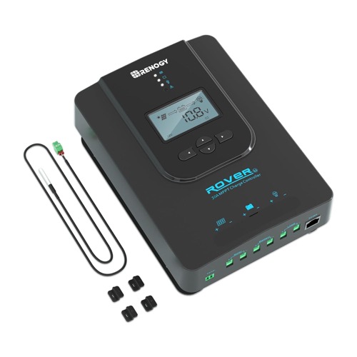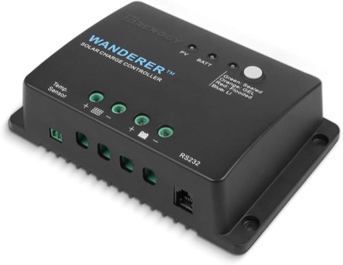

Renogy Rover vs Wanderer is an array-architecture decision before it is a price comparison. The featured Rover Li 30A converts power with MPPT and supports 12V/24V banks; the Wanderer Li 30A uses PWM and supports a 12V bank. Their shared 30A label does not make them substitutes.
The useful first question is where the panel operates relative to the battery voltage. A higher-voltage array may make Rover essential. A small, deliberately voltage-matched array can give Wanderer a sensible job without requiring every feature of the more capable controller.
This article stays with the two featured Li variants. Other Rover or Wanderer sizes can have different displays, terminals, battery voltages and communications accessories. Published limits and the exact manual govern the design; the calculations illustrate the reasoning rather than promising a measured output gain.
Renogy Rover vs Wanderer: Draw the Power Path
With PWM, the panel operates near battery charging voltage during the connected portion of the charging cycle. That can work well when the array was selected for a nominal 12V battery. A panel with substantially higher operating voltage cannot have its nameplate watts assumed at the lower battery voltage.
MPPT lets the panel operate at a tracked power point and converts that input into the voltage and current needed for charging. Rover therefore opens more panel and string choices. It still has input ceilings, startup requirements and conversion losses; the topology is not permission to use any series string.
The reviewed Rover’s maximum PV Voc is 100V. Wanderer’s is 25V. If the panel or cold-corrected series string exceeds 25V, the Wanderer is eliminated regardless of how little current the load uses. An electrically invalid low-cost option cannot become a valid purchase through a favorable price.
The compared Wanderer Li 30A is a 12V controller. For a 24V bank, evaluate the Rover Li 30A and its exact manual instead of borrowing specifications from a different Wanderer.
Use One Illustrative Panel to Understand the Conversion
Imagine a panel producing 100W at an operating point of 20V and 5A. If PWM operation brings it near a 14V charging point and panel current remains approximately 5A, battery-side power is around 70W before additional losses. That simplified estimate depends on the panel’s current-voltage curve and the actual conditions.
An MPPT controller converting the same 100W input at an assumed 95% efficiency would deliver around 95W, or 6.8A at 14V. This does not establish a fixed MPPT advantage for the featured models. Actual production depends on temperature, irradiance, battery state, controller behavior and how the array is matched.
The example demonstrates why comparing panel watts divided by nominal battery voltage is incomplete for PWM. It also explains why MPPT’s value can shrink on a very small, well-matched maintainer whose battery is full much of the time. The decision should follow useful energy delivered when the battery needs it.
Illustrative PWM: 14V × approximately 5A = approximately 70W. Illustrative MPPT: 100W × 0.95 ÷ 14V = approximately 6.8A. These are stated assumptions, not test results.
Let the Roof Layout Choose Between Series and Parallel
Parallel panels keep array voltage near one panel’s level while their currents add. That is often the natural architecture for a small PWM system, provided cold Voc and total current stay within the Wanderer’s limits. More current can require a larger cable, and parallel branches can introduce additional protection and combining requirements.
Series wiring adds panel voltage and keeps current near one string’s current. Rover’s higher input-voltage ceiling may permit that arrangement, reducing current along a longer PV run. Cold correction must be applied to the complete series string, and hot operating voltage must still leave useful MPPT headroom.
Shade complicates both layouts. A roof vent, roof rack or nearby tree changes the useful power pattern, and bypass-diode behavior matters. Do not promise a universal shade winner from the controller acronym alone. Draw the actual module locations and likely shadow paths, then decide whether the proposed electrical arrangement suits them.
| System context | First candidate | Why |
|---|---|---|
| Small 12V maintainer with matched modules | Wanderer Li 30A | PWM simplicity can meet a modest energy need |
| 24V bank or higher-voltage PV string | Rover Li 30A | Bank and input-voltage capability are decisive |
| Long PV run with planned array growth | Rover, conditionally | Series voltage may reduce run current after full string checks |
Treat Lithium Settings as a Separate Compatibility Test
Both product names include Li, but battery compatibility needs more than a chemistry label. Compare charge voltage, absorption behavior, float, equalization and temperature compensation with the exact battery manual. A setting suitable for one battery can be unsuitable for another chemistry or a different battery-management system.
For lithium, establish which device stops charging below the battery’s permitted temperature. A controller operating in cold air does not necessarily measure battery temperature or inhibit charging. An enclosure-temperature sensor also does not necessarily represent a battery mounted elsewhere.
Rover provides more detailed local configuration through its LCD and controls. Wanderer’s face uses status LEDs and a battery-selection button, with supported optional communications available for further functions. Check the precise settings exposed by the relevant module, firmware and app before assuming that a needed parameter can be adjusted.
Record the accepted configuration and verify it after a restart using the manufacturer’s connection sequence. If the battery manufacturer requires a control the chosen unit cannot supply, change the design or controller. Avoid relying on repeated BMS disconnects as normal charge regulation.
- Record battery model, bank voltage and charge-current limit.
- Match permitted charging stages and disable inappropriate equalization.
- Identify the actual source of low-temperature charge inhibition.
- Confirm required settings persist through the documented restart sequence.
Choose the Interface You Can Service After Installation
The Rover Li 30A offers numeric local information; the Wanderer Li 30A offers a simpler indicator interface. Neither buying decision should assume that an unrelated family member’s LCD or terminal arrangement is included. Read the delivered diagram, especially if a seller photo shows several variants.
Rover commonly uses the BT-2/RS485 communications route for compatible remote accessories; Wanderer uses the BT-1/RS232 route. These are different accessory paths. Confirm the exact controller and module compatibility before purchasing a bundle or trying to reuse an existing dongle.
Local Bluetooth range and internet monitoring are separate capabilities. Test pairing through the finished cabinet, save a configuration record and establish how you will check the system if the phone is unavailable. An independent battery monitor may answer energy-accounting questions that the controller’s panel-output history cannot.
For wiring, treat the controller as the charging branch of a larger battery system. Connect an inverter through properly protected battery distribution. Do not depend on assumed load terminals or a family-name feature when designing another load circuit. That circuit needs its own verified hardware, current limit and protection arrangement.
Buy for the Next Credible Layout, Not an Imagined Upgrade
Choose Wanderer when the 12V battery and small voltage-matched array are stable requirements, the simple interface is sufficient, and the cost difference has real value. Accept that changing to a higher-voltage string or 24V bank would require another controller and possibly other system changes.
Choose Rover when the actual panel layout needs MPPT conversion, the bank is 24V, detailed local information matters, or a documented expansion makes the wider envelope useful. Include module, cable, protection and mounting costs in the comparison rather than comparing two bare checkout prices.
Renogy Rover vs Wanderer has a clear tie-breaker: attach the module data sheets to a drawing of the bank and wiring. If that drawing fits the smaller PWM job and already meets daily energy needs, Wanderer is reasonable. If it requires voltage conversion or a wider electrical envelope, Rover earns its place.
See the Rover Li 30A review and Wanderer Li 30A review. Use Renogy’s manual library for the exact delivered revision, and the MPPT versus PWM guide for the broader topology explanation.