
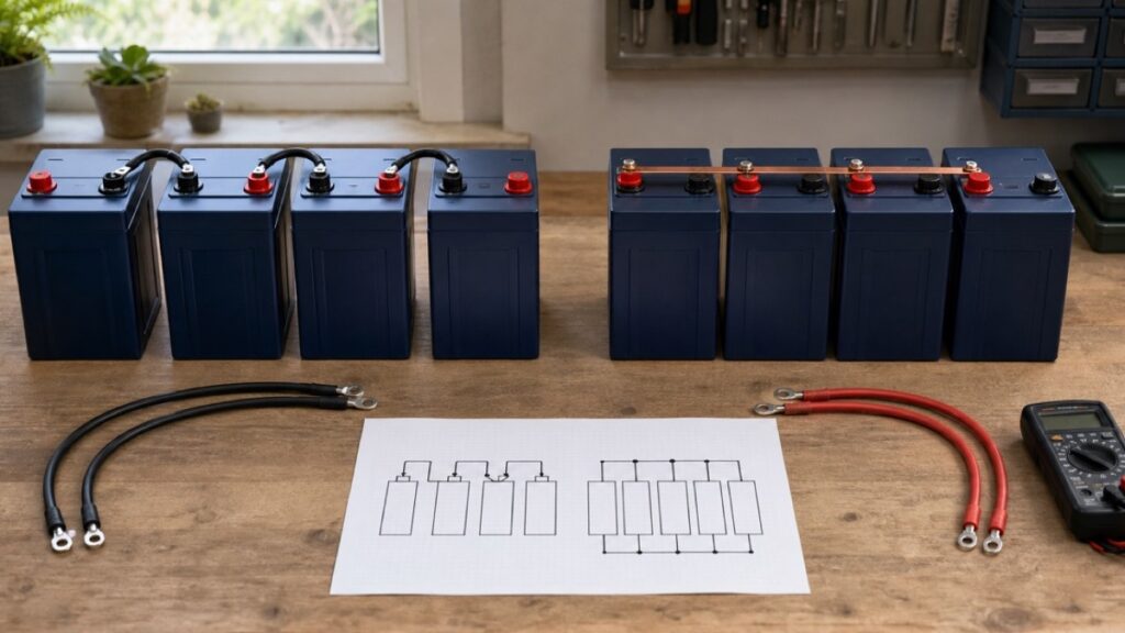
LiFePO4 batteries in series vs parallel solve different problems: series raises bank voltage while amp-hour capacity stays the same; parallel keeps voltage the same while amp-hour capacity increases. Neither is automatically better. Choose the system voltage first, confirm that the exact battery manual permits the proposed arrangement, and then design the charger, inverter, conductors, fuses, disconnects, and monitoring for that bank.
Choose series when…
Your inverter, charger, controller, and DC loads are designed for a higher bank voltage, and the exact battery explicitly allows the number of units in series.
Choose parallel when…
The system stays at the battery’s nominal voltage but needs more stored energy or current capability, and the exact manual allows that many parallel units.
The Math Changes One Dimension at a Time
Series and parallel do not create energy. They reorganize the same battery units so that voltage and amp-hour capacity appear in different combinations.
Series: bank volts = battery volts × count; bank Ah = one battery's AhParallel: bank volts = one battery's volts; bank Ah = battery Ah × countNominal bank Wh ≈ nominal volts × amp-hours
Use each product’s published nominal voltage and capacity. “12V” is a system label; a LiFePO4 data sheet may use 12.8V for the energy calculation.
Consider two hypothetical batteries, each labeled 12.8V and 100Ah. Two in series make a 25.6V, 100Ah bank: approximately 2,560Wh nominal. Two in parallel make a 12.8V, 200Ah bank: also approximately 2,560Wh nominal. Stored energy is similar, but every connected component sees a different voltage and current environment.
The higher-voltage bank can deliver the same power at lower bank current in ideal arithmetic. A 1,200W DC-side demand is about 100A at 12V but 50A at 24V before conversion losses. That can change conductor, connection, fuse, switch, and inverter choices. It does not let you reuse a 12V device on a 24V bank.
Bank charging time is still governed by energy and actual charge power. Reorganizing the same two batteries from parallel to series does not halve the stored Wh; it changes the charger voltage/current combination needed to deliver compatible power.
Start with the equipment voltage—not the batteries on sale
Write down the required nominal input voltage for the inverter, solar charge controller’s battery side, shore converter, alternator/DC-DC charger, and every direct DC load. A 24V bank with a 12V lighting circuit needs a correctly designed DC-DC conversion path; taking 12V from the midpoint of a series bank can unbalance it and is not a substitute.
If the system already exists, changing battery topology is a system redesign. “The batteries fit” is irrelevant if the converter profile, low-voltage disconnect, solar controller, inverter input range, or monitoring equipment does not match the new bank.
The Manual Is the Permission Gate
The words LiFePO4 and 100Ah do not grant a universal series or parallel limit. The internal BMS must be designed for the proposed voltage and bank behavior, and the manufacturer may limit series count, parallel count, combined arrangements, battery age difference, or supported communications.
For example, the current Battle Born BB10012 manual permits that exact model to be connected in series up to a stated 48V setup. The current Victron Lithium Battery Smart instructions publish different product-family counts and require an approved external BMS. Those facts are useful because they show why a chemistry-wide rule is unsafe—not because either limit belongs to an unrelated battery.
Can two different capacities be connected?
Do not assume so. A smaller-capacity unit in series reaches its energy boundary sooner; unmatched parallel batteries can share current and state of charge unevenly. Use only combinations the exact manufacturer approves, including rules for model, capacity, age, firmware, and initial state of charge.
Does “4S4P” on a listing settle the question?
No. Match the claim to the exact model number and current manual, then check whether 4S4P means four series units and four parallel strings, or only separate maximums that cannot be combined. Confirm required string fusing, communication, and balancing.
Can every 12V charger charge one battery inside a series bank?
Not by default. Charging one unit or taking a load from a midpoint can create imbalance and may violate the bank design. Use the bank-level charger and balancing/monitoring method approved for that exact configuration.
Do not infer compatibility from resting voltage alone. Also verify the bank’s maximum charge and discharge current, BMS reconnect behavior, temperature limits, terminal hardware, allowed orientation, and whether each battery or string requires individual protection.
Current Must Have an Equal, Protected Path
A parallel bank adds potential current paths. It does not guarantee equal sharing. Different cable lengths, conductor sizes, terminal resistance, crimps, fuse holders, or connection points can make one battery work harder than another.
Victron’s Wiring Unlimited illustrates balanced parallel-bank connection methods and explains why cable resistance matters. Treat those diagrams as engineering concepts. Your exact battery, conductor ampacity, fault-current protection, terminal stacking rules, and applicable code still control the final design.
Series strings add another balance problem
In a series string, the same current passes through every unit, but the units can reach different internal states. In a series-parallel bank, both within-string balance and between-string current sharing matter. That is why a large collection of small 12V batteries can become harder to commission and diagnose than a purpose-built higher-voltage battery system.
The fuse is not chosen from the inverter name alone. One current Victron battery manual describes matching protection to the lowest applicable rating among the conductor, battery, and system. The exact system design must also address available fault current and interruption rating. This guide cannot supply a safe universal fuse or cable size without the actual equipment, length, installation method, and code context.
Three Banks That Look Similar but Behave Differently
The following are hypothetical decision cases, not wiring instructions.
Two approved 12.8V 100Ah units in series can form about 25.6V and 100Ah. The inverter, charger, controller, DC distribution, BMS behavior, and series limit must all match. Energy is about 2,560Wh nominal.
Two approved 12.8V 100Ah units in parallel can form about 12.8V and 200Ah. Keep the RV at 12V, but redesign the branch paths, protection, monitoring, and charge capacity for the larger bank.
Two series units per string and two strings in parallel can form about 25.6V and 200Ah. The manual must permit the combined topology; each string must be matched and protected as the design requires.
Matching label values do not prove matching internal condition. Manufacturer rules for age, model, capacity, and state of charge decide whether the combination is acceptable. Replacement may require more than adding one unit.
A higher-voltage bank often reduces current for a given power, but voltage must never be selected only to make an equation attractive. Direct 12V loads, charging sources, alternator strategy, solar controller limits, monitoring, service skills, and emergency replacement availability can make a 12V parallel bank the more practical system.
Parallel can increase the bank’s documented current ceiling when the manufacturer permits additive behavior, but the installed system may still be limited by a busbar, fuse, switch, shunt, cable, connector, or inverter terminal. The bank label is not the whole current path.
Prove the Plan Before a Cable Moves
De-energized planning is the right time to find a 12V appliance on a proposed 24V bus or an unsupported battery combination. Build a one-line diagram that names every voltage domain and protective device.
- Record the exact battery model, manual revision, series limit, parallel limit, and whether combined series/parallel operation is allowed.
- Confirm all units satisfy the manufacturer’s matching requirements for model, capacity, age, state of charge, firmware, and temperature.
- Mark the nominal and permitted operating voltage of the inverter, solar controller, converter, DC-DC charger, alternator interface, monitor, and every direct DC load.
- Calculate nominal bank volts, Ah, and Wh; then separately check continuous current, surge duration, charge current, and BMS behavior.
- Draw each branch/string fuse, main protection device, disconnect, busbar, shunt, and system connection point.
- Specify conductor length, installation method, terminal hardware, torque, and interruption ratings from current documentation and applicable requirements.
- Define the approved precharge, connection, commissioning, and imbalance-response procedure before energizing the bank.
Stop if any manual is missing, the proposed combination is merely implied by a marketplace graphic, the products are unmatched, or the protection design has not been calculated. High-current battery work can cause fire, burns, or equipment damage; use a qualified RV/marine electrical professional when the design or applicable rules are outside your competence.
Your next action is not to connect the first jumper. Finish the one-line diagram, attach the exact battery manual and every charger/inverter data sheet, and have the proposed topology checked against all of them. Only then does series versus parallel become an approved system choice instead of a battery-label guess.


Leave a Reply