
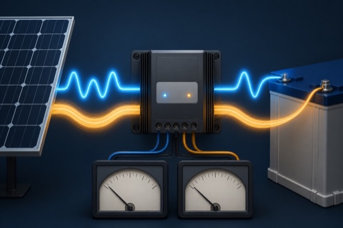
Solar charge controller voltage and amperage describe several different input and output quantities: PV Voc/Vmp/Isc/Imp, battery voltage, controller charge current, and PV watts. Compare each panel quantity only with its matching controller limit. The advertised 30A or 40A normally identifies battery-side output and does not automatically define allowed array current.
The most useful question beside an amp figure is “where?” Input current, charge current and load-output current can all have different values and limits on one device. The conversion worksheet shows why battery-side amps can exceed PV operating amps without creating energy. It uses entered operating measurements, not Voc or Isc, for that illustration.
Solar Charge Controller Voltage and Amperage Need Circuit Labels
Why a 100V/30A Controller Is Not “100V at 30A”
The two numbers usually describe different sides of the device. One can be maximum PV open-circuit voltage; the other can be maximum battery charge output. Multiplying them to claim 3,000W is wrong unless the exact documentation explicitly supports that power and context.
| Quantity | Symbol | Circuit Side | Matching Check |
|---|---|---|---|
| Open-circuit voltage | Voc | PV input | Absolute max PV voltage after cold correction |
| Max-power voltage | Vmp | PV input | MPPT operating window |
| Short-circuit current | Isc | PV input | Max PV Isc/input-current rule |
| Max-power current | Imp | PV input | Operating current/cable analysis |
| Rated charge current | A output | Battery side | Controller and battery charge limit |
| PV watts | W | Conversion envelope | Manual row for bank voltage |
Distinguish Open-Circuit Voltage From Useful Operating Voltage
Voc: The Maximum-Voltage Safety Quantity
Voc is measured with no load attached. Module Voc rises as cells get colder, so add it through a series string and apply the panel’s published temperature coefficient at the site design-low temperature.
STC string Voc = module Voc × modules in series
| Hypothetical String | STC Voc | What Remains |
|---|---|---|
| One 24V-Voc module | 24V | Cold correction |
| Two in series | 48V | Cold correction |
| Four in series | 96V | Likely too close to 100V before correction |
Vmp: The Useful Operating-Window Quantity
Vmp is the voltage near maximum power under specified test conditions. It normally falls as cells heat and changes with irradiance and operating state. MPPT needs enough PV voltage above battery charging voltage and within its stated window to track and convert effectively.
A string can pass maximum Voc yet have inadequate hot Vmp for the intended bank. This is why both top and bottom input-voltage conditions matter. Consult the controller’s startup and MPPT ranges rather than assuming any voltage below maximum will charge.
| Voltage Question | Use Voc | Use Vmp |
|---|---|---|
| Could cold string damage input? | Yes | No |
| Will hot array remain in MPPT window? | No | Yes |
| Does series count raise value? | Yes | Yes |
| Is nominal panel voltage enough? | No | No |
Keep Short-Circuit and Operating Current Separate
Isc and Imp: Two Different Array Currents
Isc is current under short-circuit test conditions and is used in equipment-input and protection calculations. Imp is current near maximum-power operation. Parallel strings add these respective values, while current through matched series modules remains approximately one module’s current.
array Isc = string Isc × parallel strings
array Imp = string Imp × parallel strings
| Configuration of Matched Modules | Voltage | Current |
|---|---|---|
| 3S1P | Three module Voc/Vmp | One module Isc/Imp |
| 1S3P | One module Voc/Vmp | Three module Isc/Imp |
| 2S2P | Two module Voc/Vmp | Two module Isc/Imp |
Apply the factors required by the exact manual, listing, and applicable rules. If maximum PV Isc is not published, request it; output charge amps are not a responsible substitute.
Follow Power Through an MPPT Conversion
Why MPPT Input and Output Amps Differ
Ignoring losses for illustration, power is approximately voltage times current. An MPPT controller can accept higher-voltage, lower-current PV power and convert it to lower-voltage, higher-current battery charging.
PV power ≈ PV volts × PV amps
battery charge power ≈ battery volts × charge amps
A hypothetical array operating at 60V and 6A produces about 360W. At a 14.4V charging target, 360W corresponds to 25A before conversion losses and limits. The PV current is 6A while battery current can be near 25A; neither number is the array Isc.
| Example Side | Volts | Amps | Approx. Watts |
|---|---|---|---|
| PV operating point | 60V | 6A | 360W |
| Idealized battery output | 14.4V | 25A | 360W |
| Real output | System-specific | System-specific | Lower/limited by conditions |
Model an Operating-Point Power Balance
A hypothetical operating point of 60V and 6A represents 360W. With 95% conversion efficiency, 342W would reach a 14.4V battery circuit before other limits, corresponding to 23.75A. The input is still 6A. That numerical difference is not evidence that either current sensor is wrong. Conversely, multiplying a controller’s 100V ceiling by its 30A charging rating would combine limits from different sides and does not establish 3,000W capability. Check each figure’s circuit location and test condition before using it.
Open calculation toolOptional · use your own values or a labelled example
Enter a PV operating voltage and current taken under the same stated condition, the battery charging voltage, and an assumed conversion efficiency. The output is an illustrative power balance before controller limits and battery acceptance. Do not enter open-circuit voltage with short-circuit current: those values do not occur together at a useful operating point.
The interactive worksheet requires JavaScript. The worked explanation below remains available; do not treat missing output as a passed check.
Educational screening only. This worksheet cannot inspect equipment, verify an installation or approve energizing.
Match the Manual Row to the Battery Bank
Battery Voltage Changes the PV-Watt Allowance
A 20A controller can handle more charging power on 24V than 12V because the bank charges at roughly twice the voltage. Manufacturers therefore publish separate PV-watt rows. Use the actual configured bank and exact model.
| Illustrative Controller Row | Meaning |
|---|---|
| 290W at 12V | Normal PV allowance when charging a 12V bank |
| 580W at 24V | Allowance for a 24V bank, not added to 12V row |
| 1,160W at 48V | Applies only if exact controller supports 48V |
Do not assume proportional values when a row is missing. Product thermal design, firmware, and input hardware can impose a different limit.
PWM Current Needs the Same Care
PWM controllers switch array connection and operate panels near battery voltage during charging. Their panel-side and battery-side current can be closer than with MPPT, but the exact PV Voc, current, power, and battery rules still apply. A nominal-12V panel label does not guarantee cold Voc fits a 25V controller.
Map the Data Sheet Before Buying
| Panel Field | Controller Field | Battery Field |
|---|---|---|
| Voc + coefficient | Absolute max PV Voc | — |
| Hot Vmp | MPPT/startup window | Charging voltage |
| Isc | Max PV Isc/input current | — |
| Pmax | PV watts at bank voltage | Max charge current |
| Connector/fuse data | Terminal/protection rules | Fault-current/protection data |
Use a worksheet and cite page/revision. Marketing bullets are useful for discovery but should not override technical manuals.
Interpret Ratings and Measurements in Their Actual Conditions
Final Interpretation Checklist
- Cold-corrected series Voc compared with max PV Voc.
- Hot Vmp compared with operating window and bank charging voltage.
- Parallel-string Isc compared with the exact PV current rule.
- Expected operating Imp used for cable/performance reasoning.
- Output amps compared with estimated charge demand and battery limit.
- PV watts checked in the correct bank-voltage row.
- Terminal, conductor, protection, and thermal constraints resolved.
How Temperature Moves the Numbers
Cold weather mainly raises module Voc, while hot cells usually reduce Vmp. Irradiance strongly changes available current and power. These effects mean a controller must survive the cold voltage extreme and still operate usefully at the hot-voltage condition.
Battery charging voltage also changes by chemistry, state, and temperature policy. Use a realistic target for output-current estimates, then rely on exact battery/controller limits for design. Nominal 12V, 24V, or 48V labels identify system classes, not fixed operating voltages.
Ratings, Recommended Values, and Absolute Limits
Data sheets can list recommended array power, nominal maximum power, absolute Voc, and protection thresholds. Preserve the label. A controller that enters overvoltage protection at 95V and has an absolute 100V ceiling should not be designed to run near either threshold in normal cold weather.
Likewise, peak efficiency is a best-case performance statement, not a current limit. Tracking efficiency, conversion efficiency, and charger efficiency can describe different calculations. None authorizes more PV Isc or a larger battery charge current.
Use Units to Catch Mistakes
Write units on every line. Volts times amps gives watts; watts divided by volts gives amps. If a calculation compares volts with watts or adds Isc to Imp, the units expose the error. Keep STC panel values distinct from measured field values and document measurement conditions.
A simple worksheet should include source page, symbol, value, unit, condition, and matching limit. This makes a review auditable and prevents a seller title from silently replacing the manual.
Four Ways an Amp Number Can Appear
The panel Imp describes normal maximum-power operation, while Isc is a test/design current. Controller PV input current may specify operating or short-circuit allowance. Controller output current limits battery charging. Finally, the battery/BMS maximum tells what the bank accepts.
All can differ in one functioning system. Ask “amps where, under what condition?” before using any value. That question resolves most misleading controller comparisons.
Read Measurements in the Controller's Current State
Open-circuit voltage is measured when the PV input is not delivering load current; operating voltage is measured while charging. Short-circuit current is a defined test quantity and should not be casually measured on an installed array. A display showing 0A can be normal at night or with a full battery, while a display showing lower-than-nameplate power can reflect ordinary field conditions.
Record irradiance, array temperature, battery voltage, stage, and loads when interpreting performance. Readings taken at different moments cannot produce a trustworthy efficiency calculation under moving clouds. App rounding and sensor location also create apparent disagreement.
Write Units and Circuit Locations on the Final Record
Current Limits Can Be Configurable but Not Erased
Some controllers allow a lower maximum charge-current setting. This can help match a small battery, but it does not increase allowable PV Voc, Isc, terminal capacity, or thermal limits. A software limit is one output control inside the hardware envelope.
Similarly, a BMS cutoff does not authorize a controller setting above the battery recommendation. Routine charging should remain within the battery’s accepted range without relying on emergency disconnection. Coordinate every source when several chargers share the bank.
Use the Same Context in Product Comparisons
Compare PV watts at the same battery voltage, Voc under the same temperature method, and Isc under the same array layout. A 1,000W claim at 48V is not larger than a 600W claim at 12V in a way that helps one fixed bank. Normalize first, then decide.
When one product omits a required value, mark it unresolved. Do not award or deduct imaginary performance. Complete documentation can be a legitimate selection advantage because it allows the system to be designed and reviewed.
The same discipline applies to customer measurements: preserve meter, location, weather, battery state, and setup. A reported 18A or 70V without those conditions cannot be transferred safely to another installation.
Finally, verify whether a displayed current is entering the battery, feeding loads, or representing array input. Interface labels can abbreviate the circuit context that the manual explains fully.
Bottom Line: Keep Every Quantity in Its Lane
Solar charge controller voltage and amperage become manageable when every value is labeled by circuit side and condition. Voc protects the input from cold overvoltage, Vmp checks operation, Isc checks input/current design, Imp describes operation, and charge amps limit battery output.
If a required quantity is missing, do not infer it from another number. Obtain exact-model documentation or use equipment with a complete boundary, and involve qualified help for conductor, protection, grounding, and fault-current decisions.
Write the final values on the system record.

Leave a Reply