
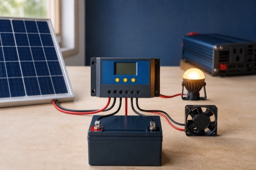
Solar charge controller load terminals are a managed DC output for suitable modest loads, often with low-voltage disconnect, timer, manual, or dusk-to-dawn control. Their current rating is separate from controller charge amps. Large inverters, motors, heaters, and other high-surge loads normally belong on a correctly protected battery-side circuit.
Treat the load output as a separate device inside the controller. Its supported voltage, continuous current, surge behavior and control method need their own evidence. The load-current worksheet compares entered demand with explicit output ratings. It does not borrow the charge-current number or assume that a brief motor surge is harmless.
Solar Charge Controller Load Terminals Have Their Own Limits
Why a 30A Controller May Not Support a 30A Load
The advertised 30A commonly describes maximum battery charging output. The load circuit may be rated 20A, 10A, 1A, or absent. It can also be electronically switched with a different surge tolerance and thermal limit.
| Rating | Circuit | Question It Answers |
|---|---|---|
| Rated charge current | Controller to battery | Maximum battery-side solar charge output |
| Load continuous current | Controller load terminals | Permitted steady load current |
| Load surge current | Load switching circuit | Whether startup/inrush is supported |
| PV Isc limit | Array to controller | Maximum panel-side short-circuit current |
Separate Managed DC Loads From Inverter Power Circuits
What the Output Can Control
Suitable uses can include DC lights, sensors, communications equipment, gate controls, or other modest loads whose voltage and current fit. The output lets the controller disconnect them when battery voltage falls, run a lighting schedule, or turn them on manually.
| Load Type | Often Suitable? | Verify First |
|---|---|---|
| LED lighting | Often | Driver inrush, voltage, dimmer behavior |
| Small router/sensor | Often | Continuous current and restart behavior |
| Gate electronics | Possibly | Motor surge may need separate circuit |
| Refrigerator/compressor | Often unsuitable | Startup surge and LVD cycling |
| Inverter | Normally no | High continuous and surge battery current |
| Heater/pump | Usually separate | Resistive or motor current and protection |
“Suitable” is not approval. The exact load manual, controller output rating, conductors, and protection decide.
Why an Inverter Usually Connects to the Battery
An inverter can draw tens or hundreds of amps at low battery voltage and briefly much more during surge. Controller load electronics are rarely designed for that path. The inverter normally uses short, correctly sized, protected battery conductors and its own disconnect arrangement.
Some controllers offer a virtual load output or communication signal that commands an external relay or battery protect device. That signal does not carry inverter current. Select switching hardware for DC voltage, continuous current, surge, and failure behavior under the exact architecture.
Understand Disconnect, Reconnect and Lighting Modes
Low-Voltage Disconnect and Reconnect
LVD turns the load off when the configured battery condition is reached; reconnect restores it later. This can reduce over-discharge but does not replace a BMS. Voltage under load includes cable drop and temporary sag, so poorly chosen thresholds can cause cycling.
| Setting | Purpose | Configuration Risk |
|---|---|---|
| LVD threshold | Protects reserve / avoids deep discharge | Too low conflicts with battery policy |
| Reconnect threshold | Restores load after recovery | Too close causes rapid cycling |
| Delay | Filters short transients | Too long may ignore real undervoltage |
| Manual override | Service or deliberate control | Can bypass intended automation |
Use battery-manufacturer guidance and understand where voltage is sensed. LiFePO4 resting voltage is relatively flat, so voltage-only state-of-charge inference can be crude. The BMS cutoff should remain a final protection, not the normal daily switch.
Timer and Dusk-to-Dawn Modes
Lighting mode often identifies darkness when PV voltage stays below a threshold, then powers the load for set hours or until dawn. Snow, shade, a PV disconnect, or unusual array voltage can influence detection. Read the model’s trigger and delay logic rather than assuming sunset is sensed optically.
| Mode | Typical Behavior | Commissioning Test |
|---|---|---|
| Always on | Output follows LVD/protection | Confirm standby draw and reserve |
| Manual | User toggles output | Verify restart after controller reboot |
| Dusk-to-dawn | On after dark, off with PV return | Test delays and shading response |
| Dusk + timer | On after dark for programmed hours | Verify clock basis and seasonal need |
Test the selected mode without bypassing safe isolation. Record menu code and actual behavior for whoever services the system later.
Review Load Wiring and Investigate Unwanted Cycling
Conductors, Protection, and Grounding
Size load conductors for continuous and startup current, length, temperature, installation method, and voltage drop. Protect branches according to source and conductor requirements. The controller’s internal electronic protection may not replace external branch protection.
Confirm whether the output switches positive, negative, or both, and whether the system uses common-negative or another grounding arrangement. Incorrect assumptions can bypass the switching function or create parallel current paths.
| Installation Item | Exact Source | Never Assume |
|---|---|---|
| Terminal wire range/torque | Controller manual | Same as battery terminals |
| Branch protection | Circuit design/manual/code | Internal protection covers cable |
| Grounding topology | Controller/system documentation | All negatives may be bonded anywhere |
| Connection sequence | Exact manual | Universal battery-first procedure |
Troubleshooting a Load Output
When the output stays off, record battery voltage, controller state, LVD status, timer mode, PV light state, current setting, and error code. Disconnect the load by the approved procedure and determine whether the controller output recovers unloaded. Do not replace a fuse with a larger one.
| Symptom | First Check | Stop Condition |
|---|---|---|
| Output always off | LVD, mode, bank voltage, error | Polarity/damage unclear |
| Cycles rapidly | Reconnect gap, cable drop, surge | Terminal heating |
| Turns on at wrong time | PV dusk threshold/delay | Unexpected energized conductors |
| Trips on startup | Load inrush vs rating | Repeated protection event |
Budget Startup Demand and Preserve Battery Reserve
Load-Terminal Planning Checklist
- Exact physical or virtual output type is identified.
- Continuous and surge current ratings exceed the real load.
- Output is available at the configured battery voltage.
- LVD, reconnect, delay, and timer values match battery/load needs.
- Conductors, terminals, protection, and grounding are documented.
- The load tolerates abrupt disconnect and automatic restart.
- High-current inverter or motor paths are kept on approved battery circuits.
- Commissioning confirms mode and current without heat or recurring faults.
Design Example: Lighting Versus a Small Pump
Consider a hypothetical lighting branch drawing 3A continuously with a brief 5A driver inrush. A documented 10A load output may be a candidate after voltage, wiring, LVD, and protection checks. The same “3A” label on a small pump can hide a startup surge several times higher, making average current a poor selection value.
Measure or obtain manufacturer surge data rather than learning it through repeated controller trips. If the output has no published surge rating, ask the controller maker or use a correctly rated external battery-side circuit. A relay controlled by the load signal may solve switching logic, but its coil, contacts, flyback suppression, enclosure, and failure state need design.
Preserve Battery Reserve Intentionally
Load control is most valuable when the owner defines which energy is expendable. Security, communications, freeze protection, and convenience lighting do not all deserve the same disconnect threshold. Separate branches or supervisory control may be better than placing every small load on one terminal.
Estimate daily load energy as watts multiplied by hours, then compare it with usable battery energy and expected charging. This energy check does not choose LVD voltage, especially for LiFePO4, but it reveals whether the load plan routinely consumes the reserve.
Compare Continuous and Peak Load Demands
A hypothetical light drawing 24W at 12V requires roughly 2A before converter losses, but a pump with the same steady current may start much higher. If the peak is 8A and the documented output permits only 5A for that duration, the pump fails that gate despite an acceptable running load. Repeated load cycling can also reflect battery voltage sag or restart hysteresis. Investigate the intended control behavior before increasing thresholds or shifting the load to a different circuit.
Open calculation toolOptional · use your own values or a labelled example
Enter demand at the actual load-output voltage, including any converter input demand. A peak-current comparison is meaningful only if its duration fits the controller’s documented surge allowance. If no suitable surge specification exists, keep that duration/permission field unresolved. A virtual control output cannot carry the load current evaluated here.
The interactive worksheet requires JavaScript. The worked explanation below remains available; do not treat missing output as a passed check.
Educational screening only. This worksheet cannot inspect equipment, verify an installation or approve energizing.
Check Virtual Outputs and Voltage-Dependent Ratings
Avoid Parasitic and Restart Surprises
Some loads draw meaningful standby current, and some reboot into a higher-power mode after interruption. Others require a manual restart, which can defeat an unattended gate or radio system. Test a complete LVD/reconnect cycle under controlled conditions and observe the load, controller, and battery response.
Dusk modes may energize a load after a PV disconnect used for service. Ensure labels and procedures account for that automatic behavior. A person isolating the array should not assume every controller output is de-energized.
Virtual Outputs and External Contactors
A virtual output can provide flexible battery-state control without carrying load current. It may drive a compatible battery protect, relay, or digital input. Confirm signal voltage/current, whether it switches high or low side, isolation, default state, and response if communications fail.
External switching does not eliminate branch protection or conductor calculations. It moves the high-current path to hardware selected for that duty. For safety-critical loads, define what happens when the controller reboots, sensor data is lost, or a contact welds.
Separate Loads When Their Priorities Differ
One load output applies one control strategy to everything connected downstream. If exterior lighting may be shed early but a communications radio must remain alive, a shared LVD threshold can be the wrong architecture. Create independently protected branches and use switching suited to each priority.
Daily energy also matters. A 6W router running continuously consumes about 144Wh per day before conversion or cable losses, while a 12W lamp running four hours consumes about 48Wh. These hypothetical figures help budget energy but do not determine wire size or LVD voltage.
daily energy = load watts × operating hours
6W × 24h = 144Wh
12W × 4h = 48Wh
Compare the total with conservatively usable battery energy and expected seasonal solar harvest. A current-compatible load can still empty the bank every night if its duty cycle was ignored.
Choose the Appropriate Protected Load Circuit
Check Output Availability Across Bank Voltages
Some controller families reduce load-terminal current at higher battery voltage or omit physical outputs on larger models. For example, a product may offer 20A at 12V/24V but only 1A at 48V. Read the exact row rather than assuming the model suffix stays constant across circuits.
Confirm whether the output is regulated to another voltage or simply switches battery voltage. Most provide the latter, so a nominal-12V accessory may see the battery’s real charging range. Use a suitable DC converter when the load requires tighter regulation, and include that converter’s standby draw, efficiency, surge, and protection in the design.
Label every automated branch with its mode and disconnect behavior. Future service should not depend on remembering which menu code energizes a seemingly dead conductor.
Bottom Line: Use the Output as a Managed Small-Load Circuit
Solar charge controller load terminals can simplify lighting and other modest DC automation, but they are not a general battery bus. Match the exact output voltage, continuous current, surge, modes, terminals, and environmental limits to the load.
If the device has high inrush, safety-critical restart behavior, or unclear grounding, design a separate protected circuit and qualified control architecture. Repeated disconnects or hot terminals require diagnosis, not a higher fuse or disabled protection.

Leave a Reply