
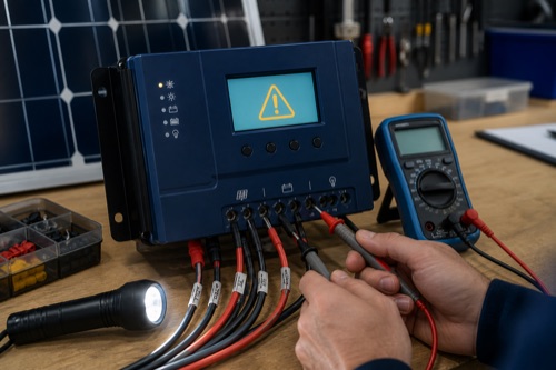
Solar charge controller troubleshooting should begin with the exact error table, a safe isolation plan, and measured PV and battery conditions — not repeated resets. Record the state before changing settings, keep Voc, Vmp, Isc, output current, and battery voltage distinct, and stop for heat, odor, damage, water, overvoltage, or recurring protective-device trips.
Start with the symptom, displayed code and physical condition. A zero-current reading with a full battery is different from zero current alongside damaged wiring. Preserve the evidence before changing settings.
Solar Charge Controller Troubleshooting Starts With a Fault Record
Build a Snapshot Before Touching Anything
Write down controller model, firmware, battery voltage/chemistry, array layout, weather, time, displayed state, error code, recent changes, and loads. This prevents a configuration change from erasing the original condition.
| Observation | Record | Why Useful |
|---|---|---|
| PV voltage/current | Display and safe independent measurement | Separates source from reporting issue |
| Battery voltage/current | At battery and controller if permitted | Reveals drop or open connection |
| Charge stage | Bulk/boost/float/storage/idle | Explains intentional current reduction |
| Temperature | Controller/battery/ambient | Tests derating or protection |
| Fault history | Exact code and timestamp | Avoids guess-based replacement |
Separate a Dark Display From an Idle Charging Stage
Controller Will Not Power On
Many controllers power their logic from the battery, so PV voltage alone may not start the display. Verify the exact manual’s minimum battery voltage, connection order, polarity, battery disconnect, fuse, and BMS state. A seemingly normal battery reading measured far from the controller can hide an open or high-resistance cable.
| Safe First Check | Likely Category | Escalate When |
|---|---|---|
| Battery voltage at controller terminals | Open fuse/disconnect, cable drop, BMS open | Polarity unclear or conductor damaged |
| Manual-required connection order | Controller not initialized | Reconnection repeats fault |
| Terminal inspection while isolated | Loose/incorrect termination | Heat or discoloration present |
| Exact model error/LED table | Known protection state | Code is absent or contradictory |
Do not bypass a fuse or protective device to “see if it works.” Determine why it opened and whether conductor or equipment damage exists.
PV Voltage Is Present but Charge Current Is Zero
The battery may be full, the controller may be in float, irradiance may be weak, or array Vmp may be too close to charging voltage. Other possibilities include reverse polarity, a disconnected string, input protection, a battery BMS opening, or a configured current limit.
| Condition | Evidence to Compare | Next Manual-Based Step |
|---|---|---|
| Battery near target | Stage, voltage, current limit | Observe expected transition |
| PV Voc normal but collapses under load | Connections, shade, damaged module | Isolate and inspect using approved process |
| Vmp insufficient | Hot-array voltage vs operating window | Reassess string architecture |
| BMS open | Battery logs/status | Resolve battery fault before reset |
An open-circuit PV reading proves little about power delivery. Voltage can appear normal through a high-resistance connection and collapse when current is requested.
Explain Low Output Before Replacing Hardware
Output Is Lower Than the Panel Nameplate
Panel watts are measured under defined test conditions. Field irradiance, angle, cell temperature, shade, dirt, cable loss, MPPT operating point, charge stage, output clipping, and controller temperature all change result. Compare input and output at the same moment and preserve units.
approximate DC input power = PV operating volts × PV operating amps
approximate battery output power = battery volts × charge amps
These calculations are diagnostic approximations, not efficiency certification. Meter accuracy, timing, controller self-consumption, and rapidly changing sun matter.
| Low-Output Cause | Clue | Do Not Assume |
|---|---|---|
| Shade/soiling | Uneven irradiance, visible obstruction | Controller failure |
| Hot modules | Lower Vmp on hot day | Voc label is operating voltage |
| Full battery | Later charge stage | Array cannot produce power |
| Clipping/derating | Output plateaus, high temperature | More panels will increase peak output |
Treat Battery and Thermal Protection as Stop Signals
Battery Reaches Wrong Voltage or BMS Disconnects
Stop charging if measured voltage may exceed the battery instruction. Verify selected profile, bank-voltage detection, remote-sense wiring, cable drop, stage timers, equalization, temperature logic, and meter accuracy. Read both controller and BMS logs before changing several settings.
For LiFePO4, a high-cell disconnect can occur while pack-average voltage looks plausible because of imbalance. A cold-charge block can produce zero current even when controller temperature is warm. The battery manufacturer, not a generic profile, defines the safe response.
Overvoltage, Overtemperature, or Repeated Trip
Use the exact error definition. PV overvoltage requires the corrected string design to be rechecked; simply waiting for warmth does not make an over-limit string acceptable. Overtemperature calls for load, ambient, clearance, terminal, and derating review, not directing a household fan at damaged equipment.
| Fault | Safe Evidence | Stop/Escalate Condition |
|---|---|---|
| PV overvoltage | Array configuration and cold Voc worksheet | Design exceeds ceiling |
| Controller overtemperature | Ambient, clearance, output, terminal heat | Damage, odor, repeated derating |
| Battery overvoltage | Independent measurement, profile, sensing | Battery limit exceeded |
| Fuse/breaker repeats | Fault-current investigation | Never replace with larger device casually |
Distinguish Communications Faults From Load-Output Faults
Display or App Data Looks Wrong
Confirm exact accessory compatibility, port type, controller power, firmware, phone permissions, pairing method, and radio range. Similar connectors can use different protocols. A lost app connection does not prove charging stopped, and a live app does not prove the measured values are correct.
Compare displayed battery voltage with an appropriate meter at the same points. Large difference can indicate calibration, sensing, cable drop, or connection issues. Do not probe exposed energized terminals beyond your training and equipment rating.
Load Terminals Do Not Energize
Check whether the model has physical load terminals, their voltage/current rating, LVD state, reconnect threshold, timer or dusk mode, manual override, and battery-voltage restrictions. A 20A charging controller can have a different load rating.
Disconnect unsuitable high-surge loads and diagnose them on their intended protected circuit. Inverters normally connect to the battery-side distribution, not the controller output.
Build a Reproducible Service Record
A Disciplined Diagnostic Flow
- Record model, firmware, array, bank, state, codes, weather, and recent changes.
- Use the exact manual to plan isolation and identify expected readings.
- Inspect for physical damage before measuring.
- Verify battery presence and polarity at the permitted point.
- Verify PV voltage/polarity and compare with the array worksheet.
- Identify charge stage and configured current/voltage limits.
- Check BMS status and other charge sources.
- Compare app/display readings with safe independent evidence.
- Change one documented variable at a time and record the result.
- Stop after any recurring fault rather than entering a reset loop.
Separate Measurement Error From Equipment Error
A clamp meter may not resolve low DC current accurately, leads can be in the wrong jack, and measurements taken seconds apart can reflect changing sun. Verify instruments and compare simultaneous readings where practical. Record units and measurement points; “the voltage was 14” is incomplete without location and controller state.
Controller apps may round values or update slowly. Battery voltage at the controller can differ from voltage at the battery under current because of cable drop. That difference can be diagnostic, but probing high-energy terminals is not appropriate without training and rated equipment.
After a Recent System Change
If the fault began after adding panels, recalculate corrected Voc, Isc, watts, and output demand. After replacing a battery, verify bank voltage detection, chemistry profile, sensor placement, and BMS communications. After rerouting cable, inspect polarity, terminal fit, strain, and voltage drop.
Firmware and app updates can change menus or communication behavior. Preserve the previous version and settings where possible, read release notes, and confirm that protective values were not reset. Do not update firmware during unstable power unless the manufacturer procedure supports it.
Intermittent Faults Need Time Context
An error appearing only at dawn may involve startup voltage or detection. A cold-clear-morning overvoltage points toward string Voc. Midday thermal reduction suggests enclosure heat, high output, or ventilation, while evening load cycling can involve LVD and cable sag.
Build a timeline with PV voltage, battery voltage, current, temperature, and state. Correlation does not prove cause, but it narrows the exact manual sections to test. Avoid replacing several components at once because the apparent improvement then has no isolated explanation.
Decide Whether Repair or Redesign Is Needed
A loose connector or wrong setting may be corrected under approved procedures. A string whose cold Voc exceeds the controller requires redesign, not repeated resets. A controller whose terminal cannot accept the calculated conductor is an equipment-selection problem rather than permission to trim strands.
When evidence points to internal failure, use warranty or qualified service and keep the unit isolated. Opening sealed electronics can void coverage and expose stored energy. Provide the manufacturer with model, serial, firmware, diagram, settings, fault history, and safe measurements rather than a vague “not charging” report.
Verify the Correction Under the Original Conditions
Confirm the Fix Without Creating a New Fault
After a documented correction, restore power only in the exact prescribed sequence and observe the same variables captured at the start. A fault that disappears without a plausible cause is not necessarily resolved. Test across the condition that originally triggered it when that can be done safely, and keep protection in place.
Compare terminal temperatures, voltage drop, charge stage, and logs over an appropriate period. Do not increase fuse size, defeat LVD, raise a voltage ceiling, or disable temperature protection to silence an error. Those changes can hide the warning while worsening the underlying hazard.
Close the record with what changed, measurements before and after, manuals used, and any remaining limitation. This creates evidence for warranty support and prevents the next person from repeating unsuccessful steps.
When the system returns to service, keep temporary test leads and covers out of the final installation. Restore barriers, strain relief, weather sealing, and labels, then verify that the normal enclosure arrangement does not recreate the original heat or communication problem.
Schedule a follow-up observation if the fault depended on temperature, shade, or battery state. Immediate success under different conditions is only a partial verification.
Keep the final diagnostic record with the system for future service and warranty evidence.
Bottom Line: Diagnose the Power Path in Order
Solar charge controller troubleshooting works best when the symptom is mapped to PV source, controller conversion, battery acceptance, load output, or communications. Preserve the original evidence, follow the exact error table, and compare each electrical quantity with its matching limit.
Low output can be normal; heat damage and unexplained overvoltage are not. When safe isolation, fault-current risk, polarity, protection, or energized measurements exceed your competence, leave the system off and involve a qualified technician.
Keep all corrective actions traceable.
Leave a Reply