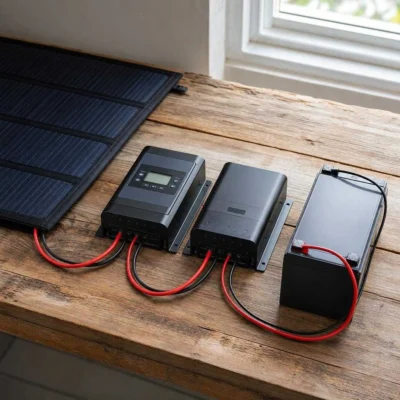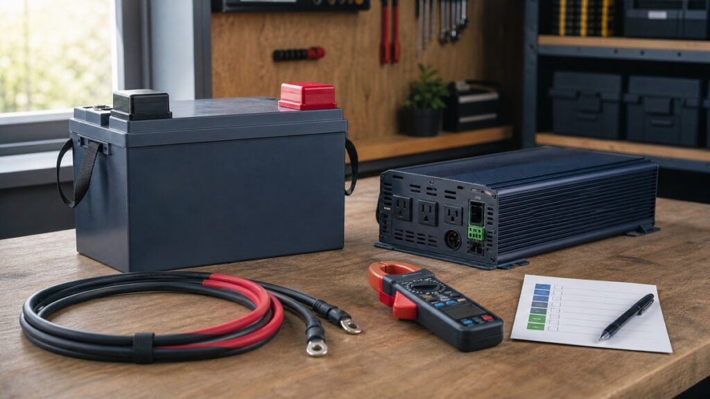
What size inverter for a 100Ah lithium battery is safe? There is no reliable inverter size from 100Ah alone. Start with the load’s running watts and startup curve, calculate battery-side current at realistic voltage and inverter efficiency, then keep both continuous and timed surge demand inside the exact battery/BMS, inverter, cable, terminal, fuse, disconnect, and temperature limits.
Convert AC Watts Into Battery Current
An inverter draws DC power and delivers AC power with losses. The preliminary current equation is:
AC load watts ÷ (battery voltage × inverter efficiency)
Use load watts, not only inverter nameplate watts. Recalculate at the inverter manual’s relevant low-voltage operating condition.
For a hypothetical 1,000W load, 12.8V battery voltage, and 90% inverter efficiency:
`1,000W ÷ (12.8V × 0.90) = about 86.8A`
At 11V under load with the same assumed efficiency:
`1,000W ÷ (11V × 0.90) = about 101A`
The AC load did not change, but lower DC voltage pushed current across a 100A boundary. Real efficiency also changes with load, temperature, and inverter design, so use the exact inverter curve or documented value instead of treating 90% as universal.
The equation does not size conductors, fuses, or an inverter. It only exposes the current that each exact component must be able to handle under the relevant condition.
Three Loads on One Nominal Battery
These hypothetical cases use 12.8V and 90% efficiency for transparent comparison. They exclude startup current and must be recalculated with exact equipment data.
Often leaves useful current headroom on a documented 100A battery, but runtime, idle draw, wiring, and appliance surge remain.
Close enough to 100A that lower voltage, efficiency, heat, and simultaneous DC loads can reverse the result.
Beyond one 100A battery’s continuous limit. A larger approved bank and complete redesign may be required.
A 2,000W inverter powering only a 200W load does not continuously draw 2,000W, but the installation must still account for its possible loads, idle consumption, surge behavior, low-voltage cutoff, and DC input requirements. Installing oversized equipment without a load-management plan can make accidental overload easier.
Likewise, a 1,000W inverter does not guarantee it can start every appliance below 1,000 running watts. Compressors, pumps, motors, and microwave electronics can impose a larger or longer startup event. Obtain the actual load data or measure it with equipment suitable for the circuit.
Power fit and runtime are separate decisions
Passing the current screen says only that the system may be able to support the load at that moment. It does not say how long the battery will run it. A hypothetical 12.8V 100Ah battery contains 1,280Wh nominally; planning around 80% usable capacity and 90% inverter efficiency would leave about 922Wh for the modeled AC load before reserve and other losses.
At a constant hypothetical 500W, that arithmetic suggests about 1.84 hours. A refrigerator or pump does not run at one constant duty cycle, while a heater may. Battery cutoff, voltage sag, temperature, inverter idle draw, wiring loss, battery condition, and concurrent DC loads can all shorten the result. Use measured watt-hours for runtime and current-versus-time data for power fit.
Waveform and output quality are separate again. A pure-sine label, neutral/ground behavior, transfer function, outlet arrangement, environmental rating, and compatibility with the actual appliance must come from the exact inverter documentation. A battery that can supply the current does not make an unsuitable inverter safe for the load.
The 100A Line Is a Boundary, Not a Target
Many current 12V 100Ah batteries publish 100A maximum continuous discharge, but that is not a chemistry rule and it is not a comfortable design target. The Battery Born BB10012, LiTime Xtra-Mini, Renogy Core Mini, Power Queen Group 24 Classic, and Redodo Basic pilot products all publish 100A continuous discharge, yet their peak-current windows differ materially.
Do not subtract headroom only on the AC side
A 12V refrigerator, fan, pump, or radio wired directly to the bank can draw current at the same time as the inverter. Charger and inverter/charger behavior can add more operating states. Inventory the total battery current path rather than treating the inverter as the only load.
Temperature and state of charge also matter. The exact product may publish derating, lower-temperature restrictions, or a BMS cutoff behavior that changes usable current. Voltage sag at high load can trip the inverter’s low-voltage protection before nominal energy is exhausted.
Parallel batteries require approved sharing
Two manufacturer-approved batteries in parallel may provide more energy and current capability, but simply multiplying one BMS rating by two assumes suitable matching and current sharing. Cable length, lug resistance, bus layout, temperature, state of charge, BMS state, and product revision can make one battery carry more current.
Use the exact battery manual’s maximum parallel count and wiring requirements. Provide branch protection and a bank layout appropriate to the available fault current and applicable requirements. A parallel bank is a designed electrical assembly, not an arithmetic shortcut.
Surge Current Has a Clock
Peak amperage without duration is incomplete. The five reviewed 100Ah batteries demonstrate very different time windows: LiTime publishes a 500A pulse for one second; Renogy publishes 300A for five seconds; Battle Born documents 200A for 30 seconds; Power Queen and Redodo documentation includes shorter or conflicting peak presentations.
- Initial instant: inverter capacitors and the load can demand a sharp current spike.
- First second: a short high pulse rating may help only if the load has already settled.
- Several seconds: a motor still accelerating needs a duration-matched battery and inverter surge envelope.
- Steady state: current must fall below every continuous limit and remain there.
A larger one-second number does not automatically beat a smaller 30-second number. Plot or obtain the load’s current-versus-time curve, then compare both magnitude and duration with the exact battery and inverter. The conductor, fuse, disconnect, terminal, and busbar path must also tolerate the intended event under their own documented behavior.
Startup repetition matters too. A surge rating may describe one event under stated initial conditions, not a compressor short-cycling every few seconds or several motors starting together. Check cooldown, duty-cycle, ambient-temperature, and overload-recovery instructions for the inverter and battery instead of assuming the published peak can repeat indefinitely.
Do not test an unknown startup by repeatedly allowing the BMS to trip. Protection activation is evidence that the design or operating state needs diagnosis; it is not a routine inverter-control method.
The Rest of the DC Path Can Say No
Even when the battery and inverter nameplates appear compatible, the components between them can set a lower limit.
Battery terminals and interconnects
Use the exact terminal hardware, engagement, lug, and torque instructions. High resistance creates voltage drop and heat, while cable weight and vibration can stress a connection.
Conductors and route
Required conductor design depends on current, length, insulation, bundling, ambient conditions, termination, voltage-drop target, and applicable rules. Copying one cable gauge from another installation is not a design.
Fuse, breaker, and disconnect
Protection must coordinate with conductor/equipment limits and safely interrupt the available DC fault current. A device’s amp label alone does not establish its interrupt rating or suitability for a lithium bank.
Inverter DC limits
Confirm nominal input voltage, operating range, low-voltage behavior, continuous and surge output, efficiency, idle draw, environmental derating, grounding/bonding, and manufacturer-required battery capacity.
High-current DC work can create fire, arc, and shock hazards. Use the exact equipment manuals and qualified design/installation whenever conductor ampacity, short-circuit current, protection coordination, grounding, or local requirements exceed your training.
The inverter’s low-voltage cutoff should coordinate with the battery BMS rather than routinely arriving after the BMS opens. A sudden battery disconnect can remove the DC reference from other equipment and complicate charging recovery. Compare both thresholds under load and include expected voltage drop between the battery and inverter.
Select From the Load Backward
Use this sequence before buying an inverter:
- List simultaneous AC loads: record running watts, power factor when relevant, and startup current versus time.
- Choose an inverter class: confirm waveform, continuous output, surge curve, outlets/hardwiring, environmental rating, and DC voltage.
- Calculate DC demand: use realistic battery voltage and exact inverter efficiency, then include simultaneous DC loads.
- Check the exact battery: compare continuous current, every timed surge boundary, temperature behavior, low-voltage cutoff, and approved bank configuration.
- Engineer the complete path: terminals, conductors, busbars, shunt, fuse/breaker, disconnect, enclosure, grounding, restraint, and applicable requirements.
- Check runtime and recharge: make sure the energy bank and charging system can support how long and how often the load runs.
The purchase gate is an evidence match, not a watt recommendation: obtain the appliance startup curve, the inverter input/efficiency/surge documentation, and the exact battery manual. If those three cannot be overlaid without crossing a current or duration boundary, change the load, inverter, bank voltage, or approved battery-bank design before installation.